Air Traffic Control
Centres
RAF Air Traffic Control
Centres
I'd mentioned the Flying
Training Control Centre established by the RAF at Ramsey, Isle of Man,
in the 1940s ATC section but there were others set up from the 1940s to
1950s. The RAF seemed to operate in a very splintered way for control,
with each command only interested their own aircraft, as FTK Bullmore had
found out when trying to set up the Flying Control Liaison Officer positions
in Fighter Command operations rooms and the Ramsey FTCC was only concerned
with training aircraft from a selected ten airfields. However, by
the early 1950s a more universal approach to providing services seemed
to be taking hold with five Air Traffic Control Centres set up at Prestwick,
Preston, Watnall, Gloucester and Uxbridge, each with a defined area of
operations, as shown on the map below.
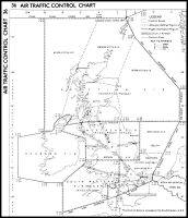
|
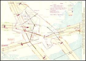
RAF Air Traffic Control
Centres
Map of areas defined
for each of the
RAF ATCCs in 1951
|
An interesting extract
from the 1951 RAF 'Radio Facilities Charts UK' handbook states the 'Aim
of the Air Traffic Control Service' as follows:
'The primary objective
of the Air Traffic Control Service is to promote the safe, orderly and
expeditious movement of all aircraft',
achieved by:
Preventing collisions
between aircraft and between aircraft and obstructions
Providing advice and
information for the safe conduct of flights
Providing distress aid
and diversion facilities
Alerting and assisting
search and rescue authorities.
For comparison the current
UK definition of Air Traffic Control Service, dating from 2012 is:
'A service provided
for the purpose of preventing collisions between aircraft, and on the manoeuvring
area between aircraft and obstructions;
and expediting and maintaining
an orderly flow of traffic.
The RAF ATCCs didn't
provide an Air Traffic Control service as we generally think of it today,
military pilots were advised to avoid Controlled Airspace is possible,
but if they needed to enter it, contact the (civil) Air Traffic Control
units responsible. An interesting statement from the 1951 book is
that:
'In the United Kingdom,
communications with the ATCCs is not mandatory, but recommended'.
So pilots could check
in with the appropriate ATCC for the area they were flying in and make
regular position reports. The ATCC would keep track of the flight
and would take 'overdue action' if a position report wasn't received when
expected. They would also provide weather reports when requested
and advise on diversion airfields if they were needed. Presumably they
would also advise pilots on other 'known' traffic that might be deemed
to be a potential hazard. The RAF ATCC used HF and VHF radio communications,
but the ATCCs were not equipped with radar sytems.
Meanwhile, after much
debate between the experts and politicians, a system for controlling civil
aircraft had been devised.
Civil Area Control
- Start of the UK Airways System
After considerable deliberation,
the UK government had decided on the future of Air Traffic Control in the
UK. Corridors of controlled airspace 'Airways' would link the major airports
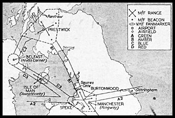
and be defined by radio beacons at strategic locations. The first airway
brought into use was 'Green One' from Strumble on the south-west Welsh
coast, via Bristol to London. Intended for use by transatlantic flights
it came into use on 1st August 1950. The second phase included more routes
around the London area, with phase three being routes northwards to Scotland
and Northern Ireland. This included airway 'Red Three' which had a segment
from Wallasey on the Wirral peninsula, over the Isle of Man and onwards
to Belfast. Initially the airways applied to aircraft flying under Instrument
Flight Rules only, aircraft flying under Visual Flight Rules were free
to fly where they wished, including across or along the airways! Subsequently,
with higher performance passenger aircraft coming into use, the Airways
were restricted to IFR flights only.
|
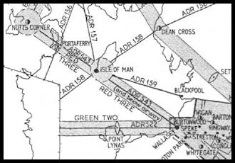
National Airways
Plan
Phase Three
Showing Airway Red Three
overhead the Isle of Man. M/F Range beacon at Cregneash with Markers at
Portaferry, Dean Cross and Wallasey.
(Diagram courtesy Flight
Global)
|
To control the new Airways,
Air Traffic Control Centres were set up in three locations, Scottish Control
at Prestwick, Preston Control in northern England and London Control at
Uxbridge, west London. These were co-located with some of the existing
RAF ATCCs, possibly for liaison purposes between civil and military but
probably more because the required teleprinter and radio facilities were
already there. In the 1951 RAF Radio Facilities book, Scottish Civil
is shown having a single VHF control frequency (120.3 MHz), Preston had
two (118.5 & 119.3 MHz) and London had four (118.9, 120.1, 120.3 &
122.1 MHz).
All of the centres had
backup HF radios available for communications with aircraft not fitted
with VHF radios.
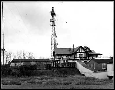 Redbrae House, Scottish
ATCC
Redbrae House, Scottish
ATCC
|
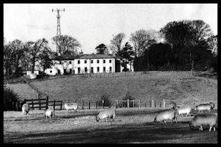 Preston ATCC
|
 Uxbridge ATCC
|
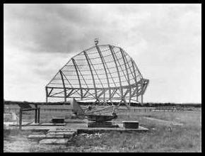
The initial radio beacons
used were Radio Ranges and Fan Markers, a proven technology used in the
USA and based on the German pre-war 'Lorenz' beam principle. The Radio
Ranges operated in Medium Frequency band and so could be received on the
radio sets as commonly fitted to aircraft of the day. The beacon radiated
on four different legs, which were aligned with the airways. They transmitted
an audible morse code 'A - .' and 'N
. -' letters, if the aircraft was left of track
the pilot would here the letter 'N' in his headphones, if right of
track the letter 'A'. When on track they would merge to a continuous tone.
It must have been quite tiring! There was a development to produce
a cockpit instrument to indicate visually if the aircraft was to left or
right of the track, the forerunner of later radio navigation instruments.
The fan markers worked on a VHF frequency of 75 Mhz and were located at
a distance along the legs of the beam and transmitted a single morse letter,
which also illuminated a light in the cockpit as the aircraft passed overhead,
providing a position fix at that point and indicate that it was time to
tune in the next beacon. In some places Radio Ranges were also used
as an approach aid to an airport. The charts below show Radio Ranges, on
the left is the London Control Zone in 1951 with three ranges and eight
Fan Markers. On the right is an approach chart for Prestwick Airport
using the Radio Range there. Click the small images for a larger
version with more information.
 The London Control
Zone in 1951
The London Control
Zone in 1951
|
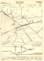 Radio Range Approach
Chart for Prestwick Airport in 1954
Radio Range Approach
Chart for Prestwick Airport in 1954
|
There is a good Wikipedia
article on Radio Ranges, including audio demonstrations.
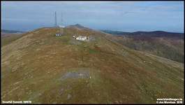
Another part of the
'Airways' system was establishing reliable VHF communications to cover
the routes. A network of radio transmitters and receivers was established
around the British Isles, often on high ground to increase the range of
the transmissions and Snaefell in the Isle of Man was one of the sites
chosen, linked into the Preston Air Traffic Control Centre which would
control the routes around northern England and the Irish Sea.
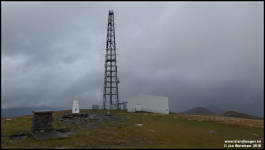 The Snaefell mast in
2018
The Snaefell mast in
2018
|
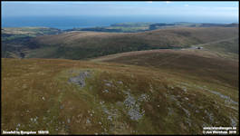
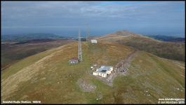 Aerial view of Snaefell
Summit in 2019
Aerial view of Snaefell
Summit in 2019
|
There is a short BBC
documentary film about the Snaefell mast and the Airways communication
system available in their archives:
BBC
Film
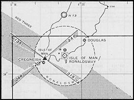
A Radio-Range was established
in the Isle of Man at Cregneash, operating on 391 Khz with an identification
of 'MYI' This radiated four 'legs', towards Belfast, Wallasey, Dean
Cross (Cumbria) and Dublin with associated Fan Markers at Wallasey, Dean
Cross and Portaferry. There was also an non directional beacon (NDB)
at Cregneash 'GCF' on 312.5 KHz, which was designed more for marine use,
operating as part of an Irish Sea network on the same frequency and transmitting
according to a set timetable, although still usable for air navigation.
|
The Cregneash Radio
Range
'MYI' 391 Khz
Showing the four 'legs'
of the range, two defining
airway Red Three. The
Isle of Man Control Zone also shown. At this point the other two legs point
out into uncontrolled airspace, but 'Advisory Routes' were to follow.
|
|
Link
to Wikipedia Article on Radio Ranges
|
Advisory Routes
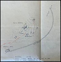
By 1956 additional Advisory
Routes had been added to the Airways System radiating from the Isle of
Man Range. ADR 157 went from the IOM northwards to Milleur Pt and catered
for the Glasgow and Prestwick flights, ADR158 went from Dublin, via the
IOM to Dean Cross and Newcastle and ADR159 went from the IOM to Blackpool.
An Air Traffic Control service was provided to participating traffic only.
Interestingly, the map shows ADRs along airway Red Three and Green Two,
was this the changeover point to banning VFR flights along airways at times?
|
|
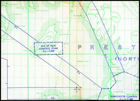
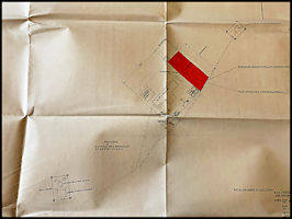
Control Zone Change
Also published in 1956,
this RAF planning chart shows the Isle of Man Control Zone has been changed
to a rectangular shape, dimensions
22nm x 10nm
|
|
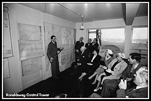
ATC at Ronaldsway
A fascinating black
and white film of Ronaldsway ATC has come to light and you can view it
on YouTube. Uploaded by Manx National Heritage it shows the day to
day operation of Air Traffic Control together with a description of how
the Instrument Landing Sytem works, which dates it to the mid or late 1950s.
Unfortunately there's no sound on the film which was apparently shot by
Airport Commandant Eric Cheshire. Ronaldsway
ATC Film
Whilst Ronaldsway retained
the Control Zone, the rules regarding its use had changed somewhat. Instead
of 'QBI' being declared by ATC, it was now up to the pilot to decide if
he could fly using the Visual Flight Rules (VFR) or needed to use Instrument
Flight Rules (IFR). If operating under VFR, the pilot could proceed into
the zone without permission, using the Rules of the Air to keep clear of
other aircraft. If operating IFR he needed to call ATC and obtain a clearance
into the Control Zone and obey ATC instructions.
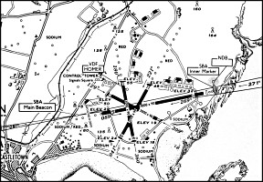
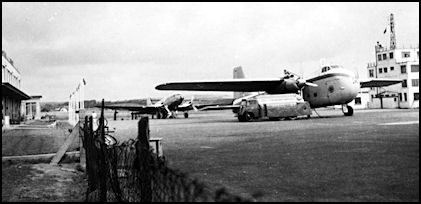
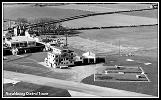 Control Tower and
ATC Signals Square - 1953
Control Tower and
ATC Signals Square - 1953
|
 BEA Dakota by the
Control Tower - 1950s
BEA Dakota by the
Control Tower - 1950s
|
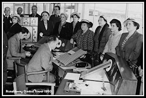
Control was carried
out from the second floor of the tower, the Navy 'Watch
Office' on the roof not appearing to be used operationally, probably due
to insufficient space for Controller, ATC clerks, radio operators and Direction
Finder operators who required to be in close proximity due to the ATC systems
in use at the start of the decade. At first Control was by either Medium
Frequency or VHF radio, with ground direction finders and radio reports
from aircraft being the only means of determining aircraft positions. Flight
Progress strips came into use in this era showing aircraft details and
having control instructions written on them, probably required with the
setting up of the airways and the need to record clearances issued by Preston
Centre. The M/F services including the direction finding station were withdrawn
from use on March 1st 1951 as more aircraft were equipped with VHF radios.
A former Royal Navy FV5 VHF Direction Finder was installed on the airfield,
this gave a remote indication of aircraft bearings directly to the controller
on a CRT indicator in the Control Room, although changing the radio frequency
used was evidently sufficiently complicated to warrant a log book entry
every time! A Pneumatic Lamson Tube system was used to connect the different
sections within the tower building, ATC, the Met Office and Teleprinters.
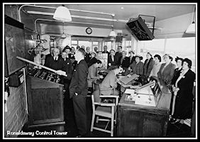 ATC Control Room
- 1950s
ATC Control Room
- 1950s
|
 Former RN 'Watch
Office' on the roof
Former RN 'Watch
Office' on the roof
|
 Enlarged view of
the Control Desk
Enlarged view of
the Control Desk
|
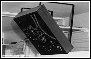 Airfield Lighting
'Mimic' on the ceiling
Airfield Lighting
'Mimic' on the ceiling
|
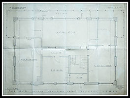 1958 Floor Plan of
Control Room Area
1958 Floor Plan of
Control Room Area
|
Radio Aids
Ronaldsway was equipped
with Medium Frequency Non Directional Beacon (NDB) 'GJE' (the old
w/t radio callsign for Ronaldsway) operating on 322 KHz and SBA 'Standard
beam Approach' on runway 27, also coding 'GJE', operating on 33.3 Mhz (the
chart below in fact shows 38.6 MHz, so the frequency was probably changed
at some point) with an Inner Marker beacon on 38 MHz. SBA was a development
of the pre-war 'Lorenz' approach aid developed in Germany and installed
at Croydon Airport in the 1930s. SBA gave similar audio indications to
the radio range, providing what we now know as a Localizer approach to
the runway. It could also provide a rudimentary glideslope indication on
a cockpit instrument, the pilot choosing which of several paths to follow
down.
Radio and Navigation
aids frequencies.
From an RAF Radio Facilities
book dated December 1951
|
Radio Telephony/Telegraphy
Ronaldsway Approach
119.7 MHz
Ronaldsway Tower 118.7
MHz 3255 KHZ. 116.1 MHz (mil emergency) 121.5 (civ emergency)
Ronaldsway Homer (VHF
direction finder) 119.7, 116.1 & 121.5
Jurby Tower 104.76,
117.9. (also 118.7 for diversions from Ronaldsway)
Jurby Homer (VHD direction
finder) 104.4,116.1 & 121.5
Met broadcast (from
Preston) 404.5 KHz, 3953 KHz, 8942 KHz
Navigation Aids
Ronaldsway NDB 'GJE'
322 KHz
Ronaldsway Standard
Beam Approach (SBA) 'GJE' 33.3 Mhz
Ronaldsway SBA Inner
Marker 38 MHz
Isle of Man Radio Range
(Cregneash) 'MYI' 391 Khz (with three remote Fan Markers on 75 Khz)
Cregneash 'Z' Marker
75 MHz
Cregneash NDB 'GGF'
312.5KHZ (Marine but available to aviation)
Douglas (Carnane?) NDB
'GGP' 291.5 KHZ (Marine but available to aviation)
Area Control
Preston Airways (civil)
(c/w Morse, c/s 'MYP') 3980/3985 KHz, 4415 KHz
Preston Airways (civil)
(AM voice) 118.5 MHz (FIR), 119.3 MHz (airways) 3270 KHz (backup to VHF)
Preston Centre (military)
(c/w Morse, c/s 'MYP') 3165 KHz, 4415 KHz
Preston Centre (military)
(AM voice) 106.02 MHz, 116.1 MHz, 121.5 MHz
|
The Standard Beam
Approach Procedure
The initial approach
to the airfield could be made using one of several aids, probably mainly
the 'GJE' NDB or by bearings from the ATC Direction Finding unit, descending
to a height not below 3,900 feet. Quite possibly, the Radio range
at Cregneash could also be used. On arriving overhead the airfield the
pilot would fly a course of 091 degrees outbound letting down to a height
of 1,555 feet and after three minutes perform a 'procedure turn' to the
right, to establish on the inbound course of 271 degrees. He would maintain
the centreline by listening to the Morse code from the main beacon. If
he was too far to the right he would hear a Morse letter 'N' (dash dot)
and if too far to the left a Morse letter 'A' (dot dash). On the
centreline the two letters would merge together to give a continuous tone.
Once established inbound, descent would be commenced at a rate of 400 feet
per minute, flying at 120 knots, down to a minimum height of 300 feet.
This could be maintained until passing overhead the Main Beacon, an Inner
Marker beacon just inside the airfield boundary indicated that the runway
threshold was just ahead. If the runway was not sighted a missed
approach was flown, climbing ahead to a height of 2,700 feet.
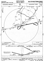 SBA Approach Chart
for Ronaldsway
SBA Approach Chart
for Ronaldsway
|
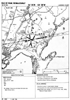 1954 Ronaldsway Landing
Chart
1954 Ronaldsway Landing
Chart
|
 Ronaldsway Airport
1954
Ronaldsway Airport
1954
|
Non-directional
Beacon and Direction Finder Approaches
There would have
also been approaches published based on the 'GJE' NDB for both runways
27 and 09. The FV5 VHF Direction Finder could be used to provide instrument
approaches to aircraft not equipped to use radio navigation aids, either
a pilot interpreted 'D/F Approach' or a controller interpreted 'QGH Approach'
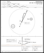 Chart for pilot interpreted
D/F Approach
Chart for pilot interpreted
D/F Approach
|
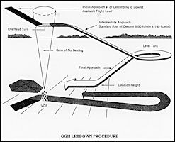 Diagram of controller
interpreted QGH Approach
Diagram of controller
interpreted QGH Approach
|
Ballahick
Radio Station
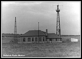 The Ballahick Transmitting
Station - 1958
The Ballahick Transmitting
Station - 1958
|
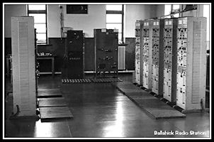 Inside the Ballahick
Transmitting Station
Inside the Ballahick
Transmitting Station
|
Transmitter frequencies
at Ballahick in 1958 were:
1190 Khz (Point to Point
& Emergency)
126.7 MHz Approach
121.5 MHz Emergency
Instrument
Landing System Installed at Ronaldsway
ILS was an upgrade on
the previously used Standard Beam Approach systems. It had three
elements, the Localizer (LLZ) that operated on VHF frequencies (100 MHz)
and provided lateral guidance along the final approach path, the Glideslope
(GS) which used UHF (300MHz) frequencies and provided vertical guidance
along the Localizer course, usually indicating a three degree approach
angle. Marker Beacons operating on low VHF (75MHz) provided position
fixes at set distances from touchdown, up to three might be provided, the
Outer, Middle and Inner Markers. When the aircraft passed over them
a light illuminated in the aircraft cockpit plus an aural tone if selected.
The Outer Marker was quite important as it co-incided with the point at
which the aircraft should start descending on the Glidesolope, early ILS
systems in particular could produce 'false Glideslopes' so it was important
for pilots to know they were intercepting the correct one. The was
usually also a Non Directional Beacon associated with the ILS, which was
where the procedure started from.
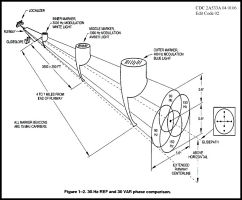 Diagram of an ILS
system with three Marker Beacons
Diagram of an ILS
system with three Marker Beacons
|
By 1955 an ILS
was commissioned on runway 27 at Ronaldsway. It would appear that initially
only the Localizer (LLZ) was installed and operational. This was likely
due to the need for the Outer Marker, which would normally be installed
directly beneath the final approach track between 4 and 5 miles from the
runway, for Ronaldsway's runway 27 this would have put it in the sea! An
Inner Marker beacon was however installed close to the threshold of the
runway. In the 1960s a solution was found and an offset Outer Marker beacon
was placed on Santon Head, allowing the Glideslope to be used.
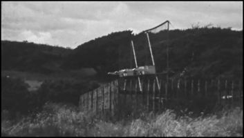 ILS Outer Marker
beacon at Santon Head
ILS Outer Marker
beacon at Santon Head
|
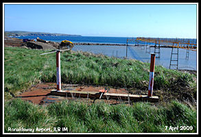 ILS Inner Marker
Aerial
ILS Inner Marker
Aerial
|
The full ILS would give
pilots an accurate indication of both lateral (Localizer) and vertical
(Glidepath) position on final approach, displayed on a Course Deviation
Indicator instrument in the cockpit. The Localizer aerial was at the far
end of the runway with the Glidepath aerial by the side of the runway close
to the touchdown point. With this precision system, landings could be accomplished
in much poorer weather conditions than before. The SBA continued in operation
for non ILS equipped aircraft.
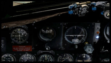 ILS Course Deviation
Indicator & Marker Beacon lights - Douglas DC3
ILS Course Deviation
Indicator & Marker Beacon lights - Douglas DC3
|
RAF Jurby
Although RAF Jurby had
closed in 1947, the airfield remained under care and maintenance and was
re-opened in 1950 as No 1 Initial Training School, where prospective RAF
pilots and navigators underwent an 18 week (later increased to 24 week)
basic course covering such subjects as navigation, meteorology, aerodynamics
and radio. Being a military unit, other important subject covered included
drill, outdoor sports and leadership exercises. There was no flying training
in the syllabus but some gliding experience was available using Sedburgh
gliders. The 'Station Flight' operated an Avro Anson for communications
purposes and possible also a DHC Chipmunk for air experience flights. Anson
VM418 came to an unfortunate end on the 6th September 1953 when it crashed
into Clach Ouyr, near Snaefell, killing all on board including the Jurby
Commanding Officer, Group Captain Worthington and the incoming C.O. Wing
Commander Fenton. In May 1953 the unit became No 1 Officer Cadet Training
Unit.
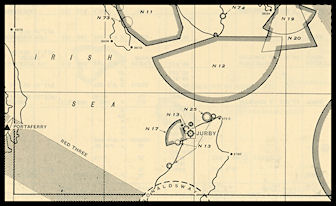 RAF 1951 area chart
centred on Jurby
RAF 1951 area chart
centred on Jurby
|
Basic ATC services were
retained at Jurby, the 1951 RAF Radio Facilities book showing that the
airfield was available on Prior Permission Only Mon - Fri 0800 - 1630 and
Saturday 0800 - 1200. Control was on 117.9 MHz with 104.76 MHz D/F by arrangement
and Military Distress frequency 116.1 MHz available with D/F. Jurby had
a light beacon available on request which would flash the letters 'JY'
in red. Sodium Approach Lighting funnels were provided for all runways
with electric runway lighting on 26/08 only.
 Jurby entry in the
Dec 1951 RAF Radio Facilities Charts Handbook
Jurby entry in the
Dec 1951 RAF Radio Facilities Charts Handbook
|
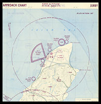 1951 Approach Chart
for RAF Jurby
1951 Approach Chart
for RAF Jurby
|
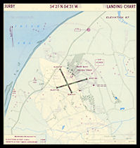 1951 Landing Chart
for RAF Jurby
1951 Landing Chart
for RAF Jurby
|
RAF Jurby was also available
for diversion from Ronaldsway, in this case the NDB beacon was radiated
on 358 KHz 'JY' and civil frequency 118.7 was manned for the diversions.
This was the same frequency used for Ronaldsway Tower. A civil control
team would be dispatched from Ronaldsway to provide the air traffic control,
using the RAF control tower. Facilities were very basic, probably consisting
of a radio set, flight progress strip board, clock and telephone.
In the Ronaldsway watch log of 26th July 1956 there is a note that a suggestion
has been made to the ATCO i/c that radio recording facilities should be
provided at Jurby as a result of the operations there on 8/7/56 as the
'written R/T log proved quite unsatisfactory'! The R/T log covering that
date has also survived and backs this up, with six pages of radio messages
recorded with a total of 43 aircraft movements between 0800 and 2200. It
seems unlikely that the requested recorders were installed.
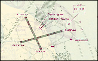 Enlarged section
of RAF chart showing Jurby Airfield
Enlarged section
of RAF chart showing Jurby Airfield
|
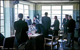 ATC facilities in
Jurby Tower
ATC facilities in
Jurby Tower
|
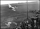
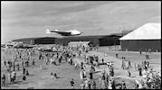
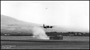
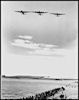
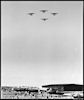
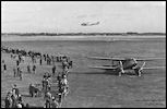
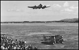
Airshows
At least one airshow
was held at Jurby during the 1950s, possible it was an annual event for
'Battle of Britain' Day.
I am indebted to Tim
Harris for the pictures below, taken 1950 - 1952 when his father, Squadron
Leader Malcolm G Harris DFC, DFM was either in command or most likely 2nd
in command of the training unit.
Air Defence Radar - The Snaefell
Radar Station
At the end of WW2 most
of the extensive radar defence network that had been established around
the United Kingdom was closed down and either dismantled or put on 'care
& maintenance'. This included the stations in the Isle of Man (see
1940s pages for details). Defence
planners had not anticipated another conflict for at least ten years and
were somewhat take by surprise by the start of the 'Cold War' towards the
end of the 1940s. It was realised that the UK was vulnerable to attack
by Soviet bombers and attempts were made to resuscitate elements of the
WW2 radar network, often without success, as was the case with the Dalby
Chain Home station in the IOM. Technicians tried to restore operations
1949 but were unable to re-activate it.
The 'Rotor' Radar
Plan
A new radar defence
network code-named 'Rotor' was devised for the UK, using some WW2 vintage
radar systems but also new ones then under development. The overall plan
used the same principles of the WW2 Reporting and Control network with
manual reporting of hostile contacts by radar stations through a 'filter'
office, plotting on an operations table and fighters controlled by separate
Ground Control of Interception (GCI) radar stations. Priority was given
to the east and south coast of the UK as this was where the greatest threat
was perceived, but 'Rotor 3' covered the west coast of the UK and this
was where the Dalby station would have been used. Instead a new location
was selected at Snaefell and construction commenced with an aim to have
the station completed and operational with a 'Stage One' radar (WW2 type
equipment) by April 1956.
It was soon realised
that the old Reporting and Control system was far too slow to deal with
jet bombers and that the new Type 80 'Green Garlic' radar could be used
for both Early Warning and Fighter Control from the same station, cutting
out the time consuming 'middle man' of the filter system. This new concept
made many elements of the originally planned Rotor system redundant, including
the Snaefell station. The Type 80 radar installed at Killiard Point in
N. Ireland could cover the whole area on it's own and it is possible that
the Snaefell station didn't even become operational. A large 'Type R11'
Operations block was constructed adjacent to the Bungalow station on the
Snaefell Mountain Railway, but siting the actual radar aerial here would
have resulted in severe screening from the surrounding hills in most directions
so the most likely location would been on the summit.
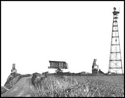
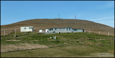 Snaefell Radar Station
- 2005
Snaefell Radar Station
- 2005
|
The Snaefell station
was designated as a Chain Home Extra Low (CHEL) and equipment provided
for these was either a Type 7 or Type 14 radar. The Type 7 operated on
a frequency of around 200 Mhz and had a large square mesh aerial that probably
wouldn't have survived the winds on Snaefell so most likely a Type 14 radar
would have been specified, a centimetric radar operating in the 10 Cm band.
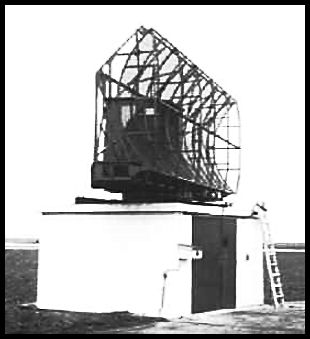 Plinth mounted Type
14 radar
Plinth mounted Type
14 radar
|
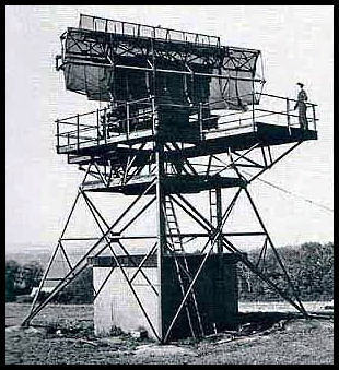 Type 14 radar mounted
on a gantry
Type 14 radar mounted
on a gantry
|
Whether the radar was
actually installed remains open to question, but eventually the Operations
Block was used as 'Murray's Motorcycle Museum' for a while until 2005,
but is currently (2014) unoccupied. It is probably one of the best preserved
above ground Cold War 'Rotor' radar stations surviving.
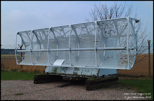 Type 14 Radar aerial
|
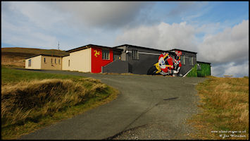 The Snaefell Radar
station buildings as repainted in 2009
The Snaefell Radar
station buildings as repainted in 2009
|
Some more recent aerial
and ground level shots of the radar station.
You can step between
pictures in this set by clicking on the arrows
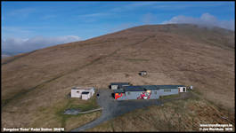 Bungalow Radar Buildings
|
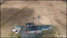 Bungalow Radar Buildings
|
 Summit - Probable
Radar Aerial Site
Summit - Probable
Radar Aerial Site
|
 Summit - Probable
Radar Aerial Site
Summit - Probable
Radar Aerial Site
|
 Summit - Ground Level
|
 Summit - Ground Level
|
(Thanks to Subterrania
Britannica and The Radar Pages
for much of the above information)
Snaefell Rotor
Radar Update (January 2020)
Researches by Chris
Corkish had produced some interesting plans for the summit of Snaefell
that appear to contradict my assumtions above!
The only actual radar
location is identified by a 'Type 54 Special Plinth' but on the opposite
side of the summit to the site with protruding ironwork as shown in the
pictures just above. I've had a quick visual look at the site on
the map but couldn't see any obvious ground marks to show that anything
was installed there. There are a few possibilities, was the
radar location changed subsequent to the plan being published ot maybe
there were plans for more than one radar, which was the common arrangement
for most of the 'Rotor' stations as in Trimingham below. The Type
54 radar used was circular dish type aerial and was normally mounted on
a 200ft high tower, but presumably the 'Special' plinth mentioned on the
plans was much lower.
There is another location
on the plans quite close to the Trig pillar on the summit, but just identified
as '25 foot Gantry and associated building' with a hard standing for a
crane, was this a potential location for a Type 14 radar? The plans
are reproduced below, if any reader have more information, I would love
to hear it!
 Snaefell Summit plan
for the Rotor aerials.
Snaefell Summit plan
for the Rotor aerials.
|
 Plan showing potential
aerial locations.
Plan showing potential
aerial locations.
|
 Trimingham 'Rotor'
Radar Aerials
Trimingham 'Rotor'
Radar Aerials
|
Radar for ATC?
With the establishment
of the post war civil ATC system, research was being undertaken on the
use of radar for controlling air traffic. In 1952 a wartime vintage
Type 14 Search Radar and Type 13 Height Finder were installed at London
Heathrow airport for evaluation. The Height FInder was not found
to be particularly useful as, unlike in an Air Defence scenario, the ATC
controller could always just ask the pilot for his current height!
The Ministry of Civil Aviation also had a wartime Type 11 radar on trial
at Heathrow which offered some interesting possibilities for ATC.
This radar operated in the 50 Cm wavelength band at around 600 MHz and
had been modified to incorporate a 'Moving Target Indicator'. This
MTI was a major advance in radar technology as it removed the ground clutter
that had always been a factor in earlier radars. With earlier equipments,
this clutter could extend to a range of 20 miles from the radar aerial,
obscuring aircraft returns within this area. The choice of the 50
Cm wavelength was also inspired in that it removed a lot of the clutter
produced on shorter wavelength radars by weather, particularly reflections
from falling rain.
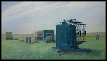 Artist's impression
of a mobile Type 11 installation
Artist's impression
of a mobile Type 11 installation
|
The Marconi company
were asked to produce an production ATC radar based on the principles of
the Type 11 and by 1954 had designed and produced the first of their S232
radars, which was installed at Heathrow for evaluation. One snag
with the S232 is that it had a horizontal beamwidth of four degrees, which
could produce a very wide 'blip' on the radar display at longer ranges.
 Marconi S232 Radar
Aerial
Marconi S232 Radar
Aerial
|
Further development
work was carried out by Marconi on the S232 design to incorporate a larger
aerial, which reduced the beamwidth from 4 degrees to a much more acceptable
2.1 degrees. This aerial was 52.5 ft long and 12 ft high in the form
of a parabolic cylinder, which was aslo easier to manufacture. New turning
gear was also produced although the electronics remained the same as in
the S232. This radar was designated the S264 and was intended to
be used as a surveillance radar for larger airports.
More information of
the use of radar in civil ATC is in the ATC
1960s section.
Area Control - Preston Air Traffic
Control Centre
The new northern Airways
were controlled from Preston Air Traffic Control Centre at Barton Hall,
to the east of the town. Area Control within the airways was by 'procedural'
means, with separation being either vertical or lateral, using time intervals
between aircraft, proved by aircraft reports over defined 'reporting points'.
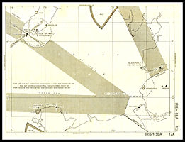 1951 Chart of Irish
Sea Airways
1951 Chart of Irish
Sea Airways
|
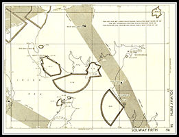 1951 Chart of Solway
Firth Airways
1951 Chart of Solway
Firth Airways
|
Preston used VHF 119.3
KHz (with H/F 3270 KHz as backup) for all its airways, with VHF 118.5 KHz
and H/F 5692 KHz available for Flight Information Service. The Flight
Information Service was the natural follow on from the old 'Communication
Areas' and would provide weather and airfield details together with information
on other aircraft know to be operating outside controlled airspace. The
RAF had their own Control Centre at Preston for control of military aircraft.
Weather reports and forecasts for Ronaldsway (and other northern airports)
were broadcast from Preston on frequencies 404.4, 3953 & 8942 Khz,
the forerunner of the present VOLMET and ATIS services. The pictures of
the ATCC below are from a later period. Preston Centre closed in
1975 and its functions were transferred to London and the new Manchester
sub centre.
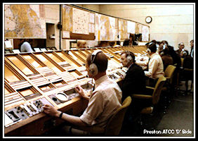
|
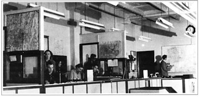
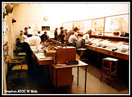
Preston Air Traffic
Control Centre 1
Controllers working
on the 'D' side of the Flight Progress Boards. Each flight had multiple
flight progress strips, placed under designators for reporting points along
the route. Colours used for area control strips were:
Blue = Westbound Flights
Buff = Eastbound Flights
Red = Airways Crossing
Flights
|
|
Preston Air Traffic
Control Centre 2
Assistants working on
the 'A' side of the Flight Progress Boards. Data Extraction Cell where
strips were produced from Flight Plan information is on the left, with
Flight Information Service controllers at the back of the room.
(Preston ATCC pictures
via GATCO)
|
|
|
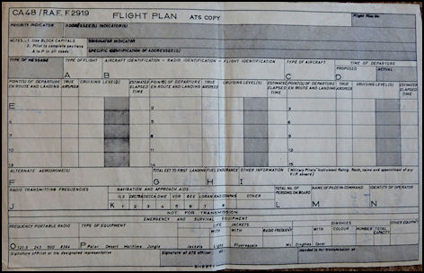
1950s Flight Plan
Form
Pilots would file their
flight plans with the ATC Flight Clearance Office at the departure airfield.
They would be transmitted via teleprinter on the Aeronautical Fixed Telecommunications
Network (AFTN) to the en-route Air Traffic Control Centres and the destination
airport. Flight Progress Strips would be hand written by ATC Assistants
and when the flight became active, displayed on the controllers Flight
Progress Boards.
|
A New Area Navigation
Systems?
Towards the end of the
decade there was international discussion to determine a new 'standard'
navigation aid system for short ranges. The British proposed an area navigation
system 'Decca Mk 10' which was based upon the wartime 'GEE' system and
could provide for any track required anywhere within the coverage of the
particular chain. Four such chains could cover the whole of the UK. It
was in use with BEA and even had a 'moving map' provision within the cockpit,
giving a continuous plot of the aircraft position. The USA wanted to continue
with their 'point source' system of VHF Omni Directional Ranges (VOR),
which required a large number of beacons and confined navigation to radials
originating from each beacon. To 'fix' an aircraft position required a
'cross cut' of radials from two beacons within range, or a newly developing
'Distance Measuring Equipment' (DME) working on UHF frequencies which when
co-located with a VOR would fix the position on a particular VOR radial
(bearing) and DME distance. The British system had far more potential at
a much lower cost, but the USA already had an extensive network of VORs
and the final decision was really a forgone conclusion. The UK would start
installing VORs and DMEs in the next decade and a true area navigation
system would have to wait for the satellite based GPS, many years in the
future.
|
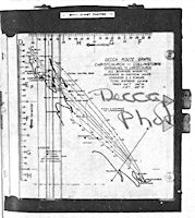
Decca Flight Plotter
Example of an early
moving map display driven by the Decca Navigator System. It used paper
charts which had to be loaded for each flight, the track of the aircraft
was drawn by pen on the map. This picture dates from 1950 of one installed
in an Airspeed Ambassador flight test aircraft.
|
1958, The Winter
Hill Disaster and Radio Beacon Identification
On the 27th February
1958, Silver City Bristol Wayfarer G-AJCS crashed into Winter Hill, Lancashire
with the loss of 35 lives. The aircraft was on a flight from Ronaldsway
to Manchester Ringway under the control Manchester Approach, having previously
been working Preston Centre. It should have been navigating to the Wigan
NDB (code 'MYK') on 316 Khz where it would have turned right to Manchester
but the first officer had inadvertently tuned in the Oldham NDB (code 'MYL')
on 344 Khz. The beacon tuning error was not noticed by either pilot
and the aircraft flew past Wigan until it eventually hit Winter Hill, close
to the television transmission mast. Neither Preston Centre nor Manchester
Approach had radar covering the initial track although the error was detected
at the last minute by the Manchester Approach Radar controller who attempted
to avert the disaster by giving an emergency turn to the aircraft, but
unfortunately it was too late. Thirty five people died and seven
were injured. Rescue attempts were hampered by deep snow on the hill.
|
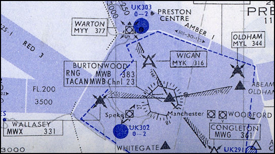
Manchester Area Airways
Chart
There are six different
medium
frequency radio beacons
located
around Manchester, all
in the 300KHz frequency range and with their morse identifications all
starting with
the letter 'M'
|
As a result of the accident
investigation it was recommended the the morse code radio identifications
of navigation aids should be changed to something like the actual name
of the location, all UK beacons at that time having a three letter identification
starting with either 'G' or 'M'. For example the Ronaldsway NDB originally
coded 'GJE' but was changed to 'RON' and then to 'RWY' The Cregneash radio
beacon coded 'MYI' and was changed to 'IOM'
|
Manx Airlines Bristol
Wayfarer G-AIMH
Picture taken around
1958, not long before the new Control Room was added to the top of the
tower
Picture by and ©
Rich Rimmer GD3YEO
|
|
New ATC Control
Room at Ronaldsway (1959)
At the end of
the decade it was decided to build a new control room on top of the old
RN Watch Office. This provided accommodation for the Aerodrome Controller,
Approach Controller and the Air Traffic Control Assistant. For the first
time all of the airfield and surrounding airspace could be seen from one
location, without having to walk outside onto a balcony!
|
|
|
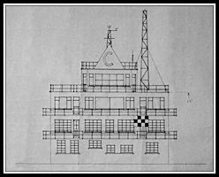 CTB Front Elevation
1958
CTB Front Elevation
1958
|
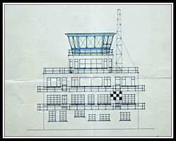 Proposed new Visual
Control Room
Proposed new Visual
Control Room
|
Installation of the
new Visual Control Room must have resulted in a major disruption to ATC
services. Apart from the physical alterations to the buildings with the
pre-fabricated room being installed on top of the former RN Watch Office,
all ATC equipment, radio aerials and the Lamson Tube system needed to be
re-located. Once in operation all ATC services were provided from the new
location. The former Control room on the third floor became another equipment
room housing radio receivers and ancillary equipment,
ATC
in the 1960s
|