1940 - 1945 under Wartime
Regulations
Ronaldsway Airport
A limited civil air
service was continued during WW2 using Dragon Rapides initially to Liverpool
and subsequently to Belfast. In July 1940 the services were transferred
to Manchester Barton but by November were back at Liverpool, which acted
as the control and authorization centre for civil Irish Sea area flights,
including those between Dublin and Liverpool operated by the Irish Airline,
Aer Lingus Teoranta. Although control of Ronaldsway Airport had been taken
over from the civil commercial operators by the UK Air Ministry, no permanent
military units were based initially and civil ATC carried on as before,
although with only two Rapides flying the Liverpool and Belfast route it
must have been rather quiet, on some days in June 1940 there are no flights
logged for days on end.
Logbook Entries,
March 1940 - click for larger
 6th March 1940
|
 7th March 1940
|
Development of RAF Air Traffic
Control in World War Two
During the inter-war
years there had been little need in the RAF for ATC as we understand it.
Most flying took place in daylight hours in good weather conditions and
aircraft recovering to land at an airfield would join overhead to observe
the signals square and then integrate themselves into other circuit traffic.
Control functions mostly concerned booking aircraft out and back in and
alerting the Crash Crew in event of an accident and would have been performed
by the 'Duty Pilot'. In the run up to World War Two, most of the
development revolved around detecting enemy aircraft and then vectoring
fighters to intercept them. After the start of WW2 when much more flying
was taking place at night and in poor weather it became apparent that a
system of control was needed to help aircraft find their way back to airfields
over a blacked out country and then not collide with other aircraft also
returning to the same airfields. The military ATC system was developed
through the war years with many specialist Air Traffic Control Officers
trained to carry out procedures as specified in document AP3024 'Flying
Control in the Royal Air Force'. Proper Control Towers were built to standard
designs, but the actual control of aircraft landing and taking off was
still carried out using light signals by the 'Airfield Controller'. He
was situated in a moveable van to the left of the downwind end of the runway
in use (where there were hard runways) but operated under the supervision
of the Flying Control Officer in the airfield Control Tower.
Air Publication 3024
- click for larger
The various RAF Commands
operated very much as separate entities, so Fighter Command wasn't interested
in what allied bombers were doing and vice-versa and neither were interested
in Training, Coastal Command or ATA ferry flights. Only Fighter Command
had access to the new radar derived information which was steadily covering
the UK, from the Chain Home early warning network to the Night Fighter
radar Ground Controlled Intercept (GCI) stations being established around
the country. Non fighter 'friendlies' were largely disregarded as
of no interest to the radar stations.
Mainly under the auspices
of F.T.K. Bullmore, a safety organisation was set up at the Air Defence
Sector Operations Rooms to guide lost bombers back to an appropriate airfield
- amazingly, initially at least, against the wishes of the air defence
organisation who were only interested in fighters and saw the air traffic
control officers in 'their' control room as a waste of space! Known as
'Flying Control Liaison Sections' they were the forerunner of today's 'Distress
& Diversion' cells and kept weather and serviceability information
on all airfields within their area and using the air defence radar plots
could often identify lost bombers and using the 'Darky' system or searchlight
direction could assist the aircraft to a suitable diversion airfield.
The 'Darky' Procedure
This was an ingenious
procedure that allowed a pilot of an aircraft in distress, whose radio
operator may have been killed or injured, to talk directly to Flying Control
at the nearest airfield. It operated by H/F R/T on a fixed frequency of
6440 Khz and transmitter powers were deliberately low to reduce range to
around ten miles. For example, a pilot requiring assistance would transmit
'Hello Darky, Hello Darky, Hello Darky, this is Koska Freddy, Koska Freddy,
over'. If Jurby Flying Control heard the call they would reply 'Hello Koska
Freddy, this is Jurby, this is Jurby, over' Once two way communications
were established assistance could be offered to home the aircraft to the
visual circuit for landing.
Searchlight Assistance
Searchlights could be
used to direct a lost aircraft towards a suitable landing airfield where
a cone of 'Sandra' lights would be illuminated as it approached to show
the location, much needed at the country was operating under blackout restrictions
at night. Other searchlights could illuminate barrage balloons if
there was a risk of friendly aircraft colliding with them. Radio 'Squeakers'
were installed on mountain tops.
The poster below
was produced to inform aircrew as to how the searchlight system worked.
Its design was instigated by Bullmore after he interviewed a lost pilot
who eventually landed at RAF Colerne more by luck than judgement after
having ignored the searchlight assistance and even a 'shepherd' Beaufighter
night fighter that intercepted him and tried to lead him to the nearest
airfield. The aircraft ran out of fuel right after landing on the
runway! The pilot said that he had seen the searchlights but didn't
know what they were for and had thought that the Beaufighter was an enemy
aircraft trying to shoot him down. There had been plenty of 'notices'
issued to flight crews about the searchlight assistance, but Bullmore realised
that a colour poster on the crew room wall would maybe stick in the mind
better. Mike Potter of the Military
Aviation Museum Virginia Beach, VA, USA has had the poster reproduced
for display in their RAF/USAAF control tower that they moved from England.
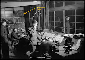 RAF Snaith control
tower with searchlight poster on wall
RAF Snaith control
tower with searchlight poster on wall
|
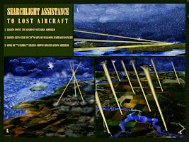 'Searchlight Assistance'
reproduction poster
'Searchlight Assistance'
reproduction poster
|
RAF Jurby
Under the 1930s RAF
Expansion Program, a military airfield was planned for the north of the
Isle of Man at Jurby, to be used for armament training. Construction started
in 1938 and initially provided a grass airfield. Paul Francis' excellent
study for Manx National Heritage records that between the 10th October
1939 and 16th January 1940 a total of 65 aircraft arrived for No 5 Air
Observers School - 21 Blenheim's, 16 Henleys, 15 Battles and 1 Magister.
On the 1st December
the unit was re-named as 5 Bombing and Gunnery School, using the same aircraft
for armament training, although reverting back to 5 AOS in July 1941. In
February 1943 the unit had 60 Avro Ansons, 21 Bristol Blenheims and 10
Westland Lysander target tugs, although the Blenheims were in process of
being retired from service. On the 1st February 1944 5 AOS was re-designated
as the Air Navigation and Bombing School and in November started to receive
a new aircraft type, the Vickers Wellington X. The unit designation was
changed again on 31st May 1945 to 5 Air Navigation School before they departed
for the UK in September 1945. After almost a year without a resident unit,
11 Air Gunners School arrived from nearby Andreas with Wellingtons, Martinets
and Spitfires in September 1946.
Although designed as
a training airfield, from November 1940 fighter units were also based,
initially 307 (Polish) Sqn with Defiant night fighters and then from January
1941, 258 Sqn with Hurricanes, being replaced in April by 312 (Czech) Sqn,
also with Hurricanes. Another squadron rotation happened in May 1941 when
312 Sqn were replaced by 302 (Polish) Sqn, again with the Hurricane, staying
until August when 457 (Australian) Sqn arrived, this time with Spitfires.
The Spitfires stayed until Andreas airfield was available and they moved
across to the in October. For a while there was a temporary Sector Operations
Room operated at Jurby as part of 9 Group, whose headquarters were at Barton
Hall, Preston, until a new operations room was opened at Ramsey, using
the gymnasium of Ramsey Grammar School.
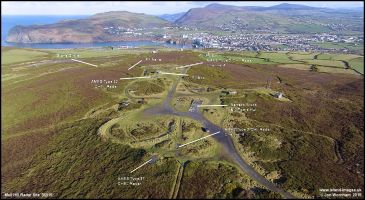
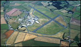 Jurby Airfield in
2001
Jurby Airfield in
2001
|
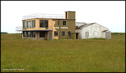 Jurby Control Tower
as preserved in 2001
Jurby Control Tower
as preserved in 2001
|
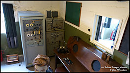
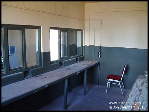 Jurby Radio Room
|
Initial ATC facilities
probably comprised the ubiquitous 'Runway Caravan', using light signals
and Very cartridges to warn aircraft of dangers on final approach, but
in the early 1940s a brick built Control Tower was added, probably at the
same time as tarmac runways were laid and electric airfield lighting installed.
Control instructions would be relayed by either telephony (R/T) or telegraphy
(W/T) using High Frequency (H/F) radio with a range of 5 to 20 miles for
R/T and 300 to 800 miles for W/T, depending on atmospheric conditions.
An H/F direction finding station would have been established close to the
airfield for providing bearings on aircraft transmissions and to enable
Controllers to provide 'QGH' let downs, homing the aircraft initially to
overhead the D/F station then on an outbound course before turning back
towards the D/F station letting down via a 'safety lane' until they
were clear of cloud and could join the visual circuit and land. As the
D/F station was remote from Flying Control, bearings obtained by the operator
had to be passed back by land line to Control before the control officer
could decide what instructions to issue. At longer ranges, communications
would have to be by H/F W/T (Morse code) via a radio operator in the tower
but at closer ranges the Flying Control Officer could use direct H/F R/T
speech although in larger aircraft the messages would be received by the
radio operator and relayed to the pilot on the aircraft intercom.
Actual control of aircraft using the runway remained with the Airfield
Controller in a caravan that was moved according to the runway in use.
Light signals using an Aldis Lamp were the preferred method of control
with Very pistol signals as a backup, the use of radio for local control
was discouraged except in emergencies.
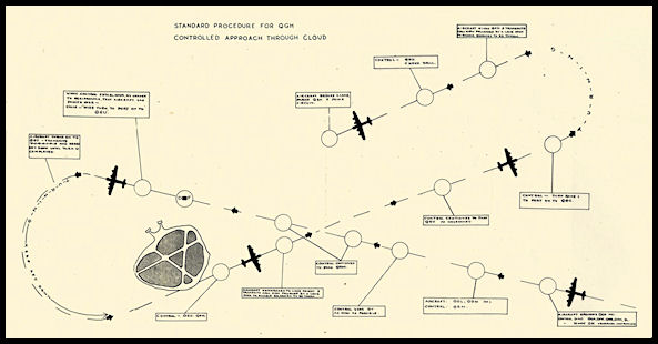 RAF 1944 QGH Approach
Procedure
RAF 1944 QGH Approach
Procedure
|
The main runway
was lengthened in late 1944 after a a series of accidents with aircraft
running off the end of the runway. The Control Tower, along with aircraft
and hangers, was badly damaged on the 20th May 1945 when a Short Sunderland
flying boat crash landed at Jurby. Although a successful landing was carried
out, after the crew had escaped depth charges on board exploded causing
extensive damage around the airfield.
On the 15th October
1947 11 Air Gunners School was disbanded and the airfield was placed under
care and maintenance for the rest of the decade until re-opened in 1950
as an officer cadet training establishment.
Preserved WW2 Control
Tower at Elvington Airfield
At the Yorkshire Air
Museum, located on Elvington Airfield to the east of York, the World War
Two Control Tower has been restored to show the typical Flying Control
provided at a bomber airfield. The facilities at Jurby Control Tower would
have been very similar.
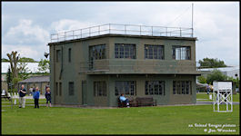 Elvington Flying
Control
Elvington Flying
Control
|
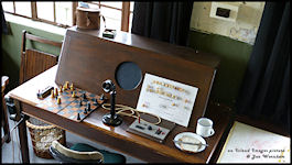 Approach Control
|
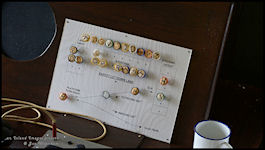 Approach Control
Pinboard
Approach Control
Pinboard
|
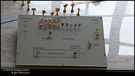 Local Control Pinboard
|
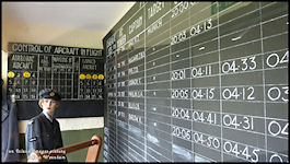 Operations Board
|
 Radio Operators Room
|
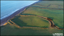
Jurby Range
As a necessary adjunct
to the training airfield at Jurby, extensive bombing and firing ranges
were established along the coastline, stretching from Orrisdale Head in
the south all the way to the Point of Ayre. By-laws were enacted
by the IOM Government in December 1939 defining the areas to be used and
regulations to be applied. They weren't always closed off to
the public and access was permitted when they were not in use, activity
being indicated by red flags flow at various locations and red lights at
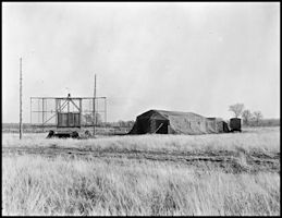
night. A total of seven 'Quadrant Towers' were erected along the
cliff tops for plotting the impact areas of bombs dropped on floating targets
located at sea. A Range Control was established in a wooden building
on the clifftop at Jurby Head, which would have been in communication with
the quadrant towers by telephone, the towers telephoning bearings of practice
bomb impacts which could then be plotted on a chart in control to show
the actual impact point. Air to air gunnery would also be practised
in the area and ranges were established at ground level for further gunnery
practice, including the Turret Training Range on Jurby Head.
The bombing targets
were triangular rafts on the sea. Constructed of wood with buoyancy tanks,
with an armour plated superstructure and a mast with a wicker sighting
mark. The actual target buoy was surrounded by three others to show
the area that the trainees were supposed to land their bombs in.
Use of the range by
aircraft would presumably have been on a time slot booking system, but
actual control was by large visual ground signals, consisting of an arrow
pointing towards the target and disks positioned at locations around it
to show whether it was safe to bomb or not.
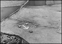 Bombing Range Ground
Signal
Bombing Range Ground
Signal
|
After WW2 finished the
range remaining in use until finally closing in 1993, the actual dimensions
of the range changed over time as indicated on the maps below.
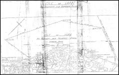 Jurby Range Plan
- December 1939
Jurby Range Plan
- December 1939
|
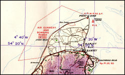 Jurby Range 1940s
|
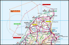 Jurby Ranges 1940
- 1993
Jurby Ranges 1940
- 1993
|
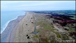 Jurby Range area
at Rue Point (2018)
Jurby Range area
at Rue Point (2018)
|
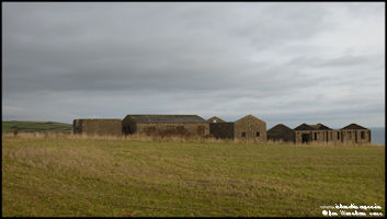
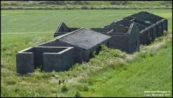
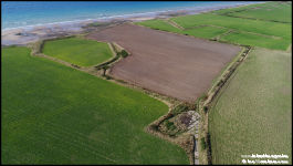 Jurby Head Turret
Training Range (2018)
Jurby Head Turret
Training Range (2018)
|
 Jurby Head Turret
Training Range (2018)
Jurby Head Turret
Training Range (2018)
|
RAF Hall Caine
Although closed as a
civil aerodrome on the outbreak of war in September 1939, Hall Caine was
taken over as a satellite airfield for RAF Jurby in the same month. It
was used as a Relief Landing Ground and to support air to air gunnery target
towing operations. The target towing aircraft would overfly Hall Caine
at 2000 ft heading out to the ranges over Ramsey Bay. After the trainee
air gunners had done their best, the target towing aircraft would fly back
to Hall Caine and drop the drogue overhead the airfield at not below 500
ft. A Control Officer was deployed from Jurby to oversee operations and
report the 'scores' back to Jurby by telephone. Aircraft used for target
towing included the Fairey Battle, Hawker Henley and Westland Wallace.
When RAF Andreas opened in 1941 the use of Hall Caine as a Relief Landing
Ground ceased but it continued to support the target towing operations
for a while. After the RAF vacated the airfield it was obstructed to prevent
possible use by enemy aircraft. After the war the airfield was returned
to its original owners and continued to be registered as an airport (albeit
with no actual flying) until 1971, although being used for a short time
in the 1990s for glider flying.
RAF Andreas
Andreas airfield was
constructed on farmland to the north east of the village and from the start
was designed as a fighter airfield to offer protection from air raids on
the cities of Manchester, Liverpool, Glasgow and Belfast. Convoy protection
work in the Irish Sea was also an important task. Construction started
towards the end of 1940 and the airfield became operational with the arrival
of 457 (Australian) Sqn from Jurby, their Spitfires arriving in October
1941. A purpose built brick control tower was provided for Air Traffic
Control to a standard RAF wartime design, but supplemented by an extra
visual Control Room on the roof, which was more usual on night fighter
stations.
 Andreas Airfield
in 2001
Andreas Airfield
in 2001
|
 Andreas Control Tower
in 2003
Andreas Control Tower
in 2003
|
In November 1941 another
unit arrived, a detachment of 275 Sqn which was a specialized Search and
Rescue unit based at Valley on Anglesey with another detachment at Eglinton
in Northern Ireland. The squadron was responsible for SAR operations over
the whole of the Irish Sea and was mainly equipped with Westland Lysanders
and Supermarine Walrus Amphibians, but also operated Defiants, Ansons and
Spitfires. 275 Sqn (det) remained at Andreas until departing back to the
UK in April 1944.
In March 1942, 457 Sqn
were replaced by another Australian unit, 452 Sqn again equipped with Spitfires,
who departed at the end of May, being replaced by 93 Sqn, many of whose
Spitfires had seen previous service with 157 and 452 Sqn. 93 Sqn remained
at Andreas until September when they departed back to the UK leaving the
island without an active fighter squadron.
An event noted in several
publications was the introduction in August 1942 of new equipment
which radically improved air to ground communications. This was probably
the replacement of the former High Frequency (H/F) radio system with the
new Very High Frequency (VHF) radios. A new remote radio station
was constructed at Regaby, about half way between Ramsey and Andreas. This
brought an major improvement in both quality and range (up to 150 miles)
of signals and enabled controllers and pilots to communicate clearly and
reliably for the first time. The equipment fitted to aircraft provided
four (sometimes eight) crystal controlled frequencies, usually arranged
as:
1) World Guard -
a frequency for common use by aircraft in need of assistance unable to
make use of any other frequency
2) Group Guard -
A frequency for common use by aircraft of the same Group when operating
together or diverted within the group
3) Sector Operational
Control - A frequency for common use by aircraft in Squadrons of the
same sector
4) Flying Control
- A frequency for Local Flying Control at the aircraft's base |
On a typical fighter
mission, an aircraft would depart using Channel 4 for communications with
Andreas Flying Control, changing to Channel 3 for direction by the Sector
Operations room at Ramsey. After the mission they would change back to
Channel 4 for recovery to Andreas. If a diversion was required and they
could make it to another 9 Group airfield, Channel 2 would be used. If
they needed to divert to a 'non Group' airfield (Ronaldsway or Jurby maybe)
they would use Channel 1. Normally, recovery into Andreas would be by visual
means but if required a 'QGH' approach could be given using Direction Finding
equipment on or adjacent to the airfield to home the aircraft through cloud
on a 'safety lane' until visual with the runways.
An additional type of
approach available to VHF equipped aircraft was the 'ZZ' procedure. This
entailed homing the aircraft to the airfield overhead and then instructing
an 'outbound' course to fly, descending to a safe level until about eight
mile away, using D/F bearings obtained every half minute to keep the aircraft
on track and timings for the range. The pilot would then be instructed
to make a 'Rate One' turn onto the correct course for landing. Again using
regular D/F bearings the pilot could be kept on the correct approach path
and instructed to descend until the controller estimates that he is approaching
the runway. A last D/F check is made and 'if the aircraft can be heard
approaching' the pilot is told 'OK to land ahead' otherwise told 'open
the throttles and climb away'. If the pilot becomes visual at any point
he may request to continue the approach visually. As in the 'QGH' procedure,
the D/F station operator was remote from the control tower and all bearings
had to relayed by land line, although in this case a 'direct loudspeaker
telephone' was mandated (From AP3024 'Flying Control in the Royal
Air Force)
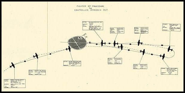 RAF 1944 'ZZ' Approach
Procedure
RAF 1944 'ZZ' Approach
Procedure
|
In May 1943 another
unit was formed at Andreas, No 11 Air Gunners School, using Miles Martinets
as target tugs and Avro Ansons equipped with turrets for training the gunners.
From September 1944 the Ansons were gradually replaced by Vickers Wellingtons
and by early 1945 the unit had also acquired twelve Spitfire VIIs for staging
fighter style attacks on the Wellingtons to train the gunners. In September
1946 11 AGS moved to Jurby and the airfield was placed on care and maintenance,
being officially closed in February 1947.
Jurby/Andreas Sector Operations
Room
As previously mentioned,
a sector operations room was established in the newly constructed Ramsey
Grammar School (West) and was operational towards the end of 1940. Originally
known as the Jurby Sector, the name was changed when Andreas airfield opened
in 1941 and the fighters moved over from Jurby. This formed part of 9 Group
whose headquarters were at Barton Hall near Preston, later to become the
home of the Preston Air Traffic Control Centre in the 1950s. The Sector
Operations room directed operations for all fighter aircraft within the
sector and was fed with information from the filter room at Barton Hall
but also direct from the radar stations on the Isle of Man. 'Chain Home'
radar stations had been established at Scarlett, Bride and Dalby and a
'Chain Home Low' station at Cregneash. Information on aircraft tracked
by the radars was supplied to the Group filter room at Preston and directly
to Ramsey, where it would be displayed in a graphical format on the Plotting
Table. The Fighter Controller sat on a raised dais overlooking the
table and direct the defending aircraft using 'Vectors' towards hostile
or unknown aircraft. Alongside the controller were assistants manning telephones
in contact with Anti Aircraft Command, Royal Navy Douglas HQ and Air Sea
Rescue. Everything that was said on the radio was recorded by clerks sitting
in four radio cabins behind the controller. Also on the site was a large
communications section with teleprinters, a cypher office and radio transmitters
and receivers. The operations room was duplicated at a remote site at Regaby,
as a backup in case the main building was bombed or otherwise put out of
service. When the interception was completed the fighters would be given
a 'Steer' back to base for recovery and instructed to contact Andreas.
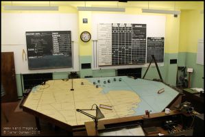 Restored Sector Operations
Room
at RAF Digby
Restored Sector Operations
Room
at RAF Digby
|
Regaby Radio Station
and standby Sector Operations Room
(Pictures courtesy of
and © Laura Mylchreest)
The need for a Sector
Operations Room for Andreas declined and in 1943 it was transferred to
Training Command to become the
Training Flying Control
Centre (see below) and operated as such until closed after the end of WW2.
Air Defence Radar
Stations
(I am indebted to the
work of Paul Francis and particularly the late Alan Cleary for much of
the information below)
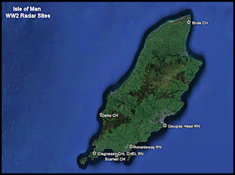 Radar Sites on the
IOM in WW2
Radar Sites on the
IOM in WW2
|
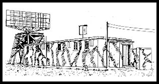
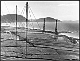 The Chain Home radar
station at Dalby
The Chain Home radar
station at Dalby
|
There were four main
Air Defence Radar sites located on the Isle of Man. At Scarlett, Dalby
and Bride, AMES Type 1 'Chain Home' (CH) radars were built, aircraft plotted
being reported to the Fighter Command Filter Room at Preston and also directly
to the Jurby/Andreas Sector Operations room at Ramsey. The first station
to be constructed was Scarlett, with work commencing in July 1940, becoming
initially operational in September.
The Chain Home radar
used large fixed transmitting and receiving towers and operated on a frequency
of 22.7 to 29.7 MHz or alternately 42.5 to 50.5 Mhz. Aircraft returns were
displayed to the operator on a Cathode Ray Tube showing range from the
station. Using Goniometers to vary input from the different receiving masts,
bearing and height could be estimated. Plotting was most accurate in range,
with bearing and height less so.
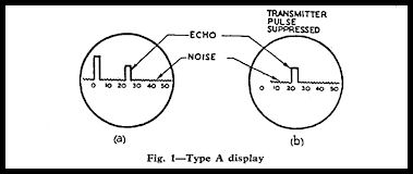 Type A display used
in CH stations
Type A display used
in CH stations
|
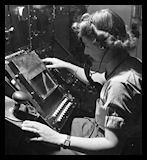 CH Operator
|
|
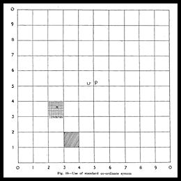
Aircraft Position
Reporting
Aircraft positions observed
were reported back by telephone using a decimal square grid system covering
the UK and surrounding waters based on an origin line at the Isle of Wight. |
The radar station at
Cregneash was quite different. Whilst the Chain Home stations were good
at detecting high flying aircraft, anything below 3000 ft would not be
plotted reliably so 'lower looking' radars were developed and these were
deployed at this site. There were a total of five radar systems installed
at Cregneash over a period of time, two AMES Type 2 Chain Home Low (CHL),
an AMES Type 52 Chain Home Extra Low (CHEL), Identification Friend or Foe
(IFF) and a Royal Navy AMES Type 31 Coastal Defence Radar.
 Aerial view of the
Cregneash Site taken in 2015
Aerial view of the
Cregneash Site taken in 2015
|
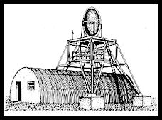
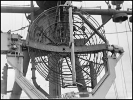
The AMES Type 2 CHL
radar worked on a frequency of 200 Mhz using a rotating five bay four stack
mesh type aerial and could detect an aircraft flying at 500 ft at a range
of 110 miles. The first Type 2 had been installed by November 1940
as a report by a visiting technician then mentions that the aerial had
been modified. He also states that it had a maximum aircraft detecting
range of 120 miles although normal range was around 40 to 45 miles. The
report mentions that the station was working 'very well' but that 'strong
winds hold up operations for long periods at this time of year'. The aerial
was manually turned and did not have a 'Plan Position Indicator' (PPI)
type display.
The next report from
the station is from May 1941 and says that the station was 'converted to
VT98s (?) common aerial and PPI at the start of the month. The PPI display
had a range of 80 miles and apart from clutter produced by the Mountains
of Mourne in Ireland worked very well. There was a problem noted
that Cregneash and Scarlett shared a land line for reporting plots to Preston
and that it was becoming overloaded and the two stations were 'competing
for its use'. It was also mentioned that two different position reporting
grids were in use, the British and Irish ones and that this was causing
confusion. It is not obvious from the report as to whether
the original Type 2 radar was modified or this was when the second Type
2 was installed on the site, quite possibly the latter to avoid loosing
radar cover while the work was carried out. The new type of aerial
was rotated electrically to feed the PPI type display.
 AMES Type 2 CHL Radar
|
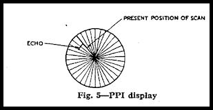 Plan Position Indicator
Display
Plan Position Indicator
Display
|
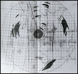 Cregneash PPI Display
Drawing 1941
Cregneash PPI Display
Drawing 1941
|
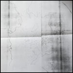 Cregneash PPI 'Plots'
Drawing 1941
Cregneash PPI 'Plots'
Drawing 1941
|
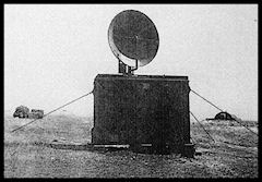
The AMES Type 52 CHEL
was a centimetric radar operating on a frequency of around 1000 MHz (3
cm or 'S' Band) with a rotating dish type aerial mounted above a nissan
hut, based on the Royal Navy 277 radar. The aim was to detect aircraft
flying below 500 ft. Returns were shown on a PPI display.
 AMES Type 52 CHEL
Radar
AMES Type 52 CHEL
Radar
|
Identification Friend
or Foe (IFF) was the forerunner of today's Secondary Surveillance Radar
(SSR) and followed on from the RAF 'Pip-Squeak' H/F D/F based system used
during the Battle of Britain to keep track of friendly fighters. IFF interrogated
a transponder fitted to friendly aircraft which produced an enhanced return
on the ground operators display to distinguish it from enemy or unknown
aircraft. The first IFF sets operated on the same frequencies as the air
defence radars, but due to the proliferation of frequencies used, a separate
band was set up just for IFF (IFF Mk III) with frequencies used in the
157 - 187 MHz band. This was the type of equipment installed at Cregneash.
The aircraft transponder receiver swept across the frequency range with
ground station allocated a spot frequency to prevent mutual interference
between stations. Aircraft transponders were only interrogated as required
to prevent the enemy using the radiated signals to home onto aircraft.
As with the Chain Home
stations, any aircraft returns observed at Cregneash were reported back
to the Filter and Sector Operation Rooms, with no actual control of aircraft
carried out from the site.
The final type of radar
at Cregneash was an AMES Type 31 Coastal Defence No1 Mk V operated by the
Royal Navy for observing ships in the Irish Sea. This was a 10 cm set very
similar to CHEL and used a parabolic dish aerial.
 Royal Navy AMES Type
31 Radar
Royal Navy AMES Type
31 Radar
|
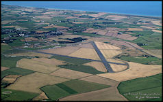
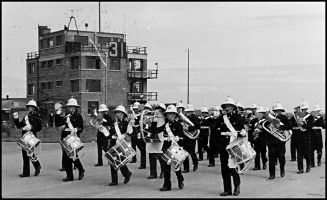
RAF Ronaldsway
Ronaldsway was requisitioned
by the RAF in May 1940 and some additional hangers constructed to
house the aircraft of the No1 Ground Defence Gunner's School which commenced
training courses in July. Aircraft used were Westland Wallaces, Hawker
Harts and Gloucester Gauntlets used for banner towing for ground to air
gunnery, with the Westland Lysander arriving later. The RAF established
a Flying Control in the airport booking office while the civil ATC continuing
to operate independently. There may also have been a 'runway van' for the
Duty Pilot, whose main duties were to fire red warning pyrotechnics or
use a signalling lamp to warn of dangers to aircraft landing, e.g. other
aircraft close by but maybe not visible to the pilot, or a machine with
retractable undercarriage approaching with the wheels still up.
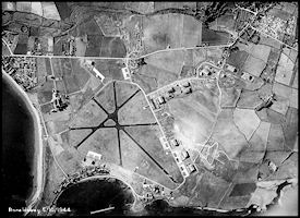
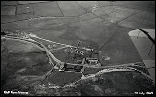 Aerial view of RAF
Ronaldsway - 31 July 1942
Aerial view of RAF
Ronaldsway - 31 July 1942
|
|
|
|
|
 Gloster Gauntlet
|
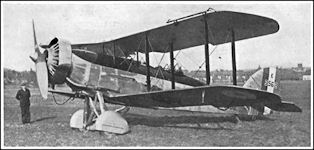 Westland Wallace
|
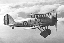
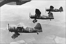 Westland Lysander
|
An RAF Direction Finding
station was built to the north east of the airfield, being able to 'home'
aircraft flying in or above cloud until they had sight of the surface and
could proceed visually to the airfield. As the station was built on a hill
some way away from the airfield it would be presumed that aircraft would
be homed to the D/F station overhead and then out to sea to let down to
circuit height. (See 'QGH' procedure under Jurby)
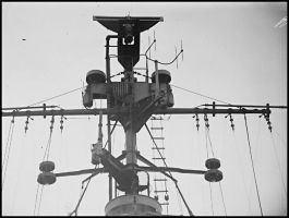
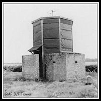 RAF octagonal D/F
Tower
RAF octagonal D/F
Tower
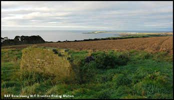 Site of the RAF D/F
station
Ronaldsway is in
the distance
Site of the RAF D/F
station
Ronaldsway is in
the distance
|
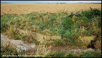 Remains of octagonal
D/F station base
at Ballafurt
Remains of octagonal
D/F station base
at Ballafurt
|
Training Flying Control
Centre, Ramsey
By 1943 the need for
the air defence Sector Operations room at Ramsey had all but disappeared
and it was converted into the Training Flying Control Centre under the
supervision of F.T.K Bullmore, who had earlier fought to establish the
Flying Control Liaison Sections. There was a huge amount of flying training
taking place from airfields around the Irish Sea and the purpose of the
centre was to keep an overall picture of the location of aircraft and offer
assistance as required. There had been problems with training aircraft
becoming lost and unable to find their way back to base and there was also
a lot of high ground creating a further hazard to aircraft 'uncertain of
their position'. Nothing like this had been attempted in UK airspace
before so Wing Commander Bullmore was in effect starting off with a clean
sheet and had to develop the unit quickly. Previously each airfield
had been responsible for their own aircraft, the idea of the TFCC was to
bring all this control under one unit, that could track individual aircraft
and offer navigation and weather advice.
Formation of Unit
From the first page
of the unit Operations Record Book, dated 3rd May 1943, the unit's purpose
was stated as:
'To improve the existing
safety organisation for aircraft of Flying Training Command carrying out
cross-country flights in the Irish Sea Area. The Control Centre at
the Sector Operations Room, Ramsey, Isle of Man for Fighter Command was
accordingly transferred to Flying Training Command, and the Training Flying
Control Centre formed. Group to be N. 29 (T) Group, Cargen House
Dumfries. Parent Unit No. 5 Air Observer's School, Jurby, Isle of Man'.
(The parent unit was changed from Jurby to Andreas by the 17th of May).
Proposed Establishment
Four Flying Control
Officers, Two Administrative Officers and one hundred and thirty one Other
Ranks.
Function
The Centre is to Control
aircraft of the following Stations:
RAF Stations: Wigtown,
West Freugh, Cark, Llandwrog (Caernarfon), Dumfries, Cranage, Jurby, Millom,
Bishops Court and Bobbington (Wolverhampton) -
within an area 52 degrees
to 57 degrees North and 2.5 degrees to 7 degrees west.
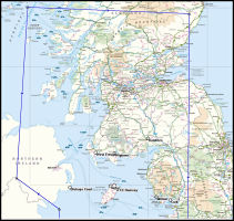 TFCC Northern Area
|
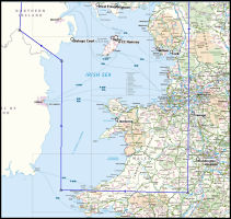 TFCC Southern Area
|
As can be seen from
the maps, the area to be covered was huge and TFCC had access to a selection
of High Frequency (HF) radio stations located around the area, some at
the airfields to be served, but others more remote, such as on the Scottish
islands of Tiree and Colonsay. As the centre had a 'Signals Interception
Unit' I would think that TFCC had direct access to the remote radio stations
which each operated on different frequencies. Most also had Radio
Direction Finding which could take bearings on aircraft transmissions.
The radio stations were probably linked by land line, but there is mention
in the Operations Record Book of a VHF station located on Snaefell and
tests being carried out to the stations around the Irish Sea. TFCC
also had a 'Command Frequency' over which instructions could be passed
to aircraft, there is a mention in the Operations Record Book for 17th
August 1943 that all Wigtown aircraft were successfully diverted to Jurby
via the Command Frequency when the weather closed in at their home base.
HF transmitting and receiving aerials were installed in the grounds behind
the control centre.
The unit was intended
to operate with one main 'large' plotting table to show the overall picture
of aircraft locations and ten subsidiary smaller plotting tables, one for
each airfield coming under the Control Centre. The Main Table was
transferred from St Angelo in Northern Ireland and was reported to be in
place by the end of June 1943 but only 'half finished'. The smaller
plotting tables were constructed specially by Fighter Command and two had
arrived in June but minus the glass coverings which were on order.
I do wonder what happened to the original plotting table at Ramsey, but
maybe it just wasn't big enough for the area to be covered.
So how did the unit
work? There were three operational sections mentioned:
|
Signals Interception
Unit
Responsible for reception
of radio messages from the aircraft and dissemination to the relevant table
in the Navigation Room. It would appear that messages were passed
(using Morse Code) in plain language or 'Q' code as there is reference
to the 'Bomber Code' being trialled but it leading to delays in positions
being plotted die to delays in decoding the messages.
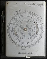
Navigation Room
(also known as the Filter Room)
The location of the
small plotting tables. The filtered radio messages would be passed
to the relevant plotting clerks who were trained to use mechanical Navigation
Computers to calculate Dead Reckoning (DR) positions of the aircraft from
their airfield. I would have guessed that standard 'Dalton' type computers
as used by aircrew would have been used, but they used 'Craig Computors',
note spelling and see pictures below. These were used to transfer
position reports onto a chart and calculate groundspeed and predict future
track. Any Radio Direction finding bearings would also passed to
the clerks who would use them to update the DR position reports.
Winds aloft could be calculated. Aircraft positions would then be
passed on to the:
Operations Room
The location of the
large plotting table and the Flying Control Officer and his support staff.
They would keep an overall watch on aircraft positions and if a particular
aircraft seemed to be going astray, contact it on the Command Frequency
and give navigational assistance. As mentioned above, Diversion Messages
could be passed to aircraft if the weather at their base became unsuitable
for landing.
|
RAF
Aircrew Navigation Computer
 RAF 1940s MK. III
Navigation Computor
Top side.
RAF 1940s MK. III
Navigation Computor
Top side.
|
 RAF 1940s MK. III
Navigation Computor
Inside.
RAF 1940s MK. III
Navigation Computor
Inside.
|
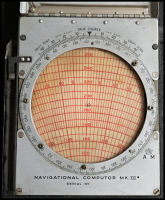
The Craig Computor
The pictures come from
an Admiralty one advertised for sale in the USA by Aero
Antique, there may have been differences from RAF ones!
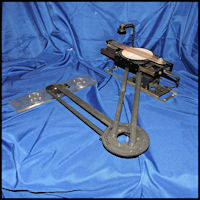 A Craig Computor
|
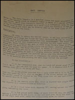 Craig Computor Description
|
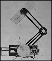 Craig Computor Diagram
|
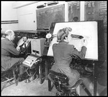 Craig Computor In
Use
Craig Computor In
Use
|
The unit seemed to suffer
from staff shortages in it's early days, although when more staff did arrive
there was then a lack of accommodation available, particularly for the
large numbers of WAAFs on the unit, and 'double bunking' is mentioned a
few times, presumably a reference to one WAAF going On Watch with the off
going WAAF taking her bunk, hardly satisfactory and by April 1944 three
extra Nissan Huts were being constructed in the grounds, hardly luxury
but an improvement!
Operations Commence
The initial period of
the unit had been involved in setting up equipment and staff training,
remember that this was a very new and novel operation, but by the 8th August
the unit went onto a 24 hour watch with one small table in use tracking
Wigtown's aircraft. By the 17th August a second table was in use,
plotting the aircraft from West Freugh, but continued staff shortages,
particularly of Radio Operators continued to restrict the unit's expansion.
It had been determined that a 'Four Watch' pattern would best suit the
unit and requests for further staff had been made to Command. By
September it is reported that ten Radio Interception watches were in operation,
although probably not over 24 hour periods. The unit gradually took
on more units, one at a time, as staff and equipment became available.
A 'Homing Searchlight'
was installed at Ramsey in August 1943, to direct lost aircraft to Jurby.
This was one of the innovations introduced by Bullmore when he was setting
up the Flying Control Liaison Sections in Fighter Command operations room
so he was probably pleased to have a local one! On the 20th September it
is reported as being successfully used for diverting aircraft to Andreas
and Jurby where they maybe had 'Sandra' searchlight cones available (see
poster below).
There are the remains
of wooden masts with climbing rungs on the top of several hills in the
Isle of Man. At least one of them used to have a fairly substantial
cast iron fixing on the top, possibly to either support a homing searchlight
or radio 'Squeaker' that emitted a low power 'Whooh Whooh' noise that would
be received on a bomber's 'Darky' radio set to warn them they were close
to high ground.
The unit must have been
very busy once it was looking after the aircraft from all ten airfields
and even before then a 'Time Recording apparatus' was installed in the
Filter Room (Navigation Room, the name seems to have changed) and an 'endless
belt system for plaques' from the Interception Unit. I'm presuming
that the radio operators recorded the messages received on the plaques
and this was the way that data was transferred to the Navigation Room.
Unfortunately the Operations
Record Book finishes on the 23rd July 1944 so I have no other details of
the unit's operations after that date. The unit's personnel strength
on that date is reported by Wing Commander Bullmore as: RAF 48 WAAF 164,
total 212. From previous reports I think this excludes commissioned
officers.
The TFCC continued operations
until after the end of WW2 in 1945. I don't have a date for closure,
but by 1951 the RAF had a total of five Air Traffic Control Centres established
in the UK (but none in the Isle of Man!) at: Gloucester, Preston, Scottish
(Prestwick), Uxbridge and Watnall. The wartime situation where each RAF
Command operated their own control systems and had no interest in other
Command's aircraft seems to have ended, with the new centres offering a
service to all RAF aircraft.
The TFCC was a truly
pioneering operation, which led on to present day Air Traffic Control Centres,
but unfortunately seems to have largely been forgotten about.
Their Majesties
the King and Queen visited the unit in October 1945 and I've included a
photo of Ramsey Grammar School (West) in 2021.
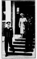 Royal Visit to TFCC
1945
Royal Visit to TFCC
1945
|
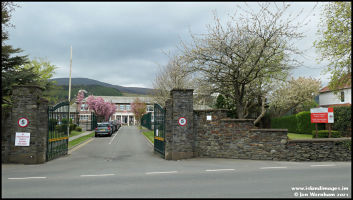 Ramsey Grammar School
West
2021
Ramsey Grammar School
West
2021
|
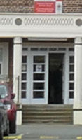 The steps seen in
first picture - 2021
The steps seen in
first picture - 2021
|
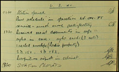
1943 - Ronaldsway Rebuilt
The RAF unit remained
at Ronaldsway under various guises until the end of March 1943 when, control
of the airfield was handed to the Admiralty and a huge reconstruction started
place to transform the relatively small grass airfield of the 1930s into
a large and very modern Fleet Air Arm airfield with hard runways suitable
to be a main training unit for the Fairey Barracuda torpedo and dive bomber
aircraft. Unlike most airfields constructed during WW2 (including Andreas)
to the standard RAF three runway pattern, Ronaldsway had four runways to
comply with admiralty requirements - crosswinds were not a problem on aircraft
carriers and so there were more choices of 'into wind' runway. The runways
were also narrower than the standard 50 yards, to simulate aircraft carrier
deck landings they were only 30 yards wide. Post war this would involve
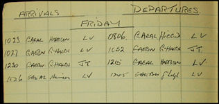
considerable work to widen two of them to civil standards. A log book entry
from 6th September 1943 mentions that Rapide G-AEAL with captain Harrison
operated off 'the runway' with full load, 'very satisfactory', however
on the 18th the same captain ran off the side of the runway in G-AFEZ
and damaged the aircraft!
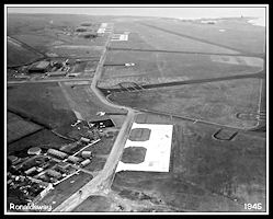
Drawings for the re-building
of Ronaldsway, dated 1944
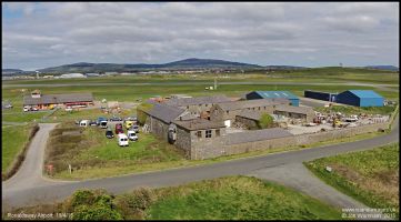
Work continued at a
rapid rate until completed in Spring 1944. During all this time the civil
air link continued operation. Construction of the runway 13/31 necessitated
demolition of the original airport buildings and on the 1st April 1944
civil ATC moved to a new location at the 'Barn Site', part of the original
Ronaldsway Farm. The original pitched roof of the barn was flattened at
one end to enable the radio receiving aerials to be located above the control
room. This may have also been the time at which the transmitters, located
to the west of the field in the 1930s, were moved to the Ballahick site
just east of Ballasalla. A logbook entry of 27th June states '6 hours overtime
re window extension', presumably a reference to the new window fitted to
the control room to improve visibility.
 Aerial shot of Ronaldsway
October 1944
Aerial shot of Ronaldsway
October 1944
|
 Aerial view of the
'Barn Site', home of Civil ATC in 1944
Aerial view of the
'Barn Site', home of Civil ATC in 1944
|
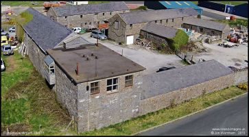 The 1944 Civil ATC
control office showing the flattened roof
The 1944 Civil ATC
control office showing the flattened roof
|
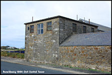 1944 Civil ATC Control
Room
at the Barn Site
1944 Civil ATC Control
Room
at the Barn Site
|
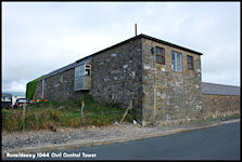 Southwest elevation
of the
Control Room
Southwest elevation
of the
Control Room
|
RNAS HMS Urley - The Royal Navy
take over at Ronaldsway
Ronaldsway Naval Air
Station was officially commissioned on 21st June 1944 under commanding
officer Captain W. P. Shirley-Rollinson.
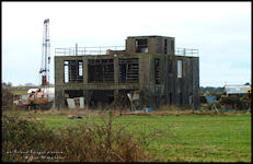
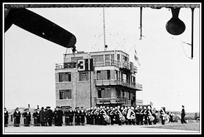
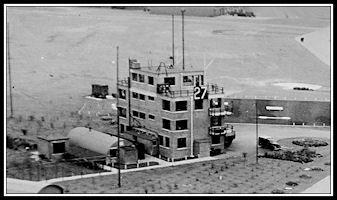
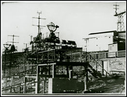
The Royal Navy were
very firmly in control of the airfield and operated from a new four storey
brick control tower on the north side of the airfield.
 The Royal Navy Control
Tower
The Royal Navy Control
Tower
|
The Air Watch
Office
On the top level of
the control tower was the Air Watch Office. This gave a good view over
the airfield and in all directions around it and all aircraft movements
on the airfield and in the circuit were controlled from here by the Petty
Officer of the Air Watch and his assistant. The room would be equipped
with VHF radios for communications with aircraft and telephone links to
all other ATC departments, not least the Runway Control Van.
The Control Room
On the floor below the
Air Watch Office was the Control Room, which kept an overall eye on all
air operations. Staffing would be the Duty Air Traffic Control Officer,
radio operators and flight loggers. The aerodrome lighting was controlled
from here and tote boards would be used to keep check of all aircraft operating
away from the station, with information on the type of sortie being operated,
aircraft and crew details and ETAs. Communications away from the
vicinity of the airfield would probably use M/F or H/F radios with W/T
(Morse) used instead of speech. VHF Direction Finding radio could
give 'steers' to incoming aircraft to assist them in locating the airfield
in poor weather. Other electronic aids were also provided as detailed
below.
The Runway Control
Van
This was a moveable
vehicle that would be positioned on a purpose built concrete loop adjacent
to the upwind end of the runway in use and moved as required. It
was staffed by two Runway Controller Petty Officers whose task was to ensure
the safety of aircraft using the runway. Light signals by Aldis lamp would
be given to confirm that it was safe to land or take off, or to indicate
that an aircraft had to 'overshoot' and re-join the circuit.
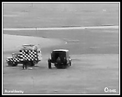 The Runway Control
Van
(and is that the
NAAFI van visiting?)
The Runway Control
Van
(and is that the
NAAFI van visiting?)
|
Remote Radio Stations
Despite the RN Control
tower seemingly equipped with a good selection of radio aerials, two remote
radio stations were established. A Transmitting station was constructed
at Orrisdale and a Receiving station at Phildraw, both locations to the
north of Ballasalla. At the moment I don't know what frequency ranges
were in use at these stations, but possibly VHF based on their subsequent
use. The Royal Navy would have removed their equipment when HMS Urley
closed in 1945 but the sites were back in use by civil ATC for VHF radiotelephony
in 1947.
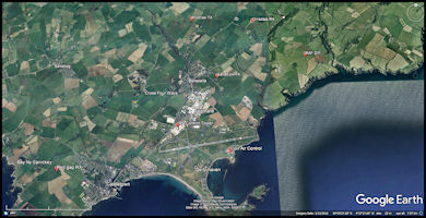 Google Earth image
showing 1940s Radio Sites
Click for larger image
Google Earth image
showing 1940s Radio Sites
Click for larger image
|
Civil ATC
Civil ATC operated from
the 'Barn Site' on the southern edge of the airfield and was primarily
concerned with ensuring the safe operation of the civil air link between
the Isle of Man, Liverpool and Belfast. They had a very restricted
view of the airfield from this location but could see the civil apron and
hanger located behind the houses of Derbyhaven. They continued to
use M/F W/T (Morse) to communicate with the DH Dragon Rapides operating
the air services, which were not fitted with the VHF radios being used
by the Royal Navy aircraft.
 The Ronaldsway civil
ATC Control window
The Ronaldsway civil
ATC Control window
|
So how were civil and
military aircraft safely controlled on the same runway when they were fitted
with completely different radios?
The Royal Navy would
decide on the Runway in Use and (usually!) communicate this to Civil ATC
so the the civil pilots would know what runway to expect. Aircraft
wishing to depart would taxy using the perimeter taxiway as far as the
holding position for the runway in use and then await a light signal from
the Royal Navy Control Van . Arriving aircraft would join the circuit,
integrating themselves visually with other traffic and observe the control
van for light signals. On turning final for the runway they would
either receive a green 'cleared to land' or a red 'overshoot' signal.
After landing they would vacate the runway and taxy to their parking locations.
By this means civil and military aircraft, totally unable to talk to each
other's control towers could be safely integrated.
There are occasional
complaints by RN ATC noted in the surviving logbooks about civil aircraft
not completing proper circuits, operating off other than the 'Runway in
Use' and blocking taxiways. As very little of the airfield could be seen
from the barn site window there was probably not a lot civil ATC could
do about this. It would seem that they was more concerned with the en-route
operation of the air link, express permissions having to be obtained from
Liverpool Speke for each individual flight. This possibly explains the
orientation of the extended window, as although most of the airfield was
out of view, the civil parking apron behind Derbyhaven Crescent was directly
ahead and the important signals requesting departure clearance and indicating
arrival of inbound flights could be sent by observing the Dragon Rapides
movements.
 Ground view of the
RN Control Tower
Ground view of the
RN Control Tower
|
 Aerial view of the
RN Control tower
Aerial view of the
RN Control tower
|
A logbook entry of 13th
July states that the RN Flying Control Orders were submitted to the civil
operators and is followed on subsequent days by several comments of aircraft
not following instructions! On the 31st there is a comment in the log 'Please
warn Sumner and any LV (Liverpool) pilot to wait for flashing green light
for taxiing and continuous green light for take-off given by airport van'
- it would seem that the civil pilots were having a little difficulty in
getting used to operating to RN regulations and having to get permission
to take off and land!
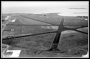
The new Ronaldsway had
four asphalt runways giving a possibility of eight landing directions,
from time to time there seemed to be a lack of co-ordination between military
and civil resulting in each believing that a different runways was in use.
Civil control was still by 'procedural' means with the help of D/F using
Medium Frequency (M/F), but the Navy had VHF R/T (speech telephony) giving
controllers instant communication to pilots.
The first Fleet Air
Arm squadron, 747 NAS arrived on the 14th July 1944, equipped with Fairy
Barracuda II aircraft, followed by 713 NAS on the 12th August, also with
Barracuda IIs. The final Barracuda squadron, 710 NAS reformed at Ronaldsway
on 7th October, equipped with Barracuda II & III, also operating the
Fairy Swordfish biplane. The three permanently based squadrons had a total
of 92 Barracudas between them out of a total of 120 naval aircraft based
at Ronaldsway. There were also several temporary detachments of squadrons
to HMS Urley, including four Miles Martinets from 725 NAS based between
August and November to provide Air to Air firing facilities. During 1945
there were two detachments from 772 NAS, normally based at Ayr, Scotland.
This squadron flew several different aircraft types including the Hawker
Sea Hurricane, Vought Corsair, Fairy Swordfish, Miles Martinet, Douglas
Boston and Fairy Firefly. Avro Ansons were also used at Ronaldsway for
initial training of Observers in the use of the Air to Surface Vessel radar
(ASV) before progressing to the faster and more advanced Barracuda.
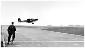
 Airfield looking
south along runway 13
Airfield looking
south along runway 13
|
 Airfield looking
SE past the RN Control Tower
Airfield looking
SE past the RN Control Tower
|
Practice Aircraft
Carrier Landings
Royal Navy aircraft
practising aircraft carrier landings would be 'batted down' by the Landing
Signals Officer
standing on the side
of the runway, dummy arrester wires were painted on the runways.
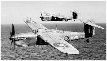 Fairey Barracuda,
Mk II nearest with Mk III behind
Fairey Barracuda,
Mk II nearest with Mk III behind
|
The Barracuda Mk II
was fitted with a metric wavelength Air Surface Vessel Radar (ASV) with
Yagi type aerials on the wings, the Mk III had a centimetric ASV with the
scanner housed in a blister under the rear fuselage. The Mk III radar was
optimized for anti submarine work.
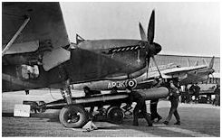 WRENs loading torpedoes
|
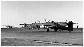 Barracudas taxy out
|
 Waiting at the holding
point
Waiting at the holding
point
|
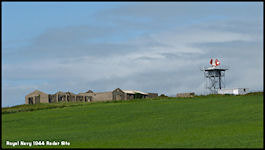
The Ronaldsway Radar Site
Until I have more information
available, the following is mainly educated guesswork!
Situated right on the
north east corner of the HMS Urley airfield, close to where the new radar
aerial (2011) is situated and now outside the airfield perimeter, are a
collection of buildings that date back to the 1940s. From aerial
photographs, they were still being constructed when HMS Urley started operations
in 1944, but seemed to be in use by early 1945. According to
a narrative by an officer who passed through the training programme here,
the bombing ranges at Port Soderick and Perwick were monitored by radar
and on the airfield plans of the time the location is identified
as the 'GCI Site' (Ground Control of Interception). As there would
be no requirement for a GCI service for the Barracuda's this would most
likely refer to the type of radar installed here, either a Royal
Navy Type 277 or more likely a Type 293. These were the usual aircraft
surveillance and fighter direction radars fitted to RN ships of the period.
(But see below for an alternative suggestion by Chris Corkish).
 1944 RN Radar Site,
with the 2011 Selex Primary Surveillance Radar site on the right.
1944 RN Radar Site,
with the 2011 Selex Primary Surveillance Radar site on the right.
|
 Radar Type 277 Aerial
|
 Radar Type 293 Aerial
|
We know that Royal Navy
radar operators were trained at HMS Valkyrie, situated on Douglas Head,
so I'm thinking that building a land based equivalent of the conditions
that they would work in at sea would make a lot of sense and where better
to construct it than right next to a RN Air Station that was training carrier
based pilots. Certainly, post WW2, such a facility was in use at
the RN air station at Yeovilton, Somerset.
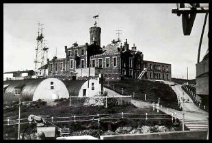 HMS Valkyrie on Douglas
Head
HMS Valkyrie on Douglas
Head
|
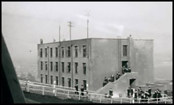 HMS Valkyrie, building
now Manx Radio
HMS Valkyrie, building
now Manx Radio
|
 Radars on Douglas
Head
Radars on Douglas
Head
|
HMS Valkyrie was
established in the 1940s as a training base for Royal Navy radar operators
and technicians. The former Douglas Head Hotel was taken over and
a substantial new building constructed nearby that is now the headquarters
and studios of Manx Radio. Trainees were accommodated in the
requisitioned Granville Hotel on Douglas promenade, right next to one of
the internment camps for 'enemy aliens' Every day they would march
(or run, according to one account!) from the promenade to Douglas Head.
As can be seen in the left hand picture above there were also Nissan huts
in the grounds. A selection of radar sets would have been installed
and some of the aerials can be seen on masts in the picture. These
look to be of the older metric wavelength type using 'Yagi' type aerials,
but on the right hand side of the picture, maybe out of shot by intent,
the object looks like it could be part of the rotation gear for a more
modern centimetric type radar scanner.
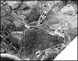 1945 Aerial Photograph
showing the HMS Urley Radar Site
1945 Aerial Photograph
showing the HMS Urley Radar Site
|
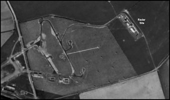 The RN Radar site
from a 1946 aerial picture.
The RN Radar site
from a 1946 aerial picture.
|
On board a RN ship involved
with aircraft operations, mainly aircraft carriers but also some other
ships, there would be an Aircraft Direction organisation occupying several
separate 'offices'. Initial information from the ship's radars would
be received in the Radar Display Room (RDR) from which plots would be telephoned
to the adjacent Aircraft Direction Room (ADR). Here together with
reports from other sources (aircraft IFF and radio direction finding for
example) they would be plotted on the rear of the Main Air Display Plot
(MADP), a large vertical perspex screen. At the other side of the
MADP, the Air Plot Officer (APO) would combine and 'smooth' the various
plots to produce a air situation display. In overall charge of the
ADR is the Direction Officer. Also in the ADR is the Intercept Officer
(IO) whose main task is to direct fighter aircraft to intercept incoming
raids. He would use the MADP to see the overall picture, but had
direct use of the ships radar to direct fighters from PPI radar displays.
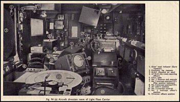 An Air Direction
Room
An Air Direction
Room
|
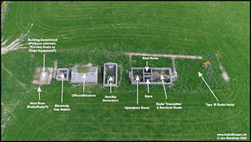
The Site Today (2017)
The only solid information
I have to date is from the remaining buildings on the site and the fact
that radar was used at Ronaldsway to observe the bombing ranges.
The buildings are quite extensive and from a few ground visits would seem
to consist of (starting from the eastern 'sea' side), an accommodation
and office block with an adjoining workshop with a large door opening.
The next building is at 90 degrees to the others with a higher roof and
probably housed diesel generators to power the site. Following is
the only building which still has a roof and internally is divided into
several smaller rooms. I'm suggesting that this is the most likely building
to house the Aircraft Direction Offices. The final building still in existence
has no roof but from aerial photographs it looks like it indeed never possessed
such, did it maybe house oil tanks for the generators? The final
area on the main site is today just an overgrown concrete base with some
steel work protruding from the ground but again, from the aerial photographs,
looks like it might have had an open lattice mast, possibly on top of a
building housing the radar transmitter/receiver and with the radar aerial
mounted at the top (it has a long shadow on one picture). There is
also a smaller building away from the main facilities which would most
likely have been a guard post.
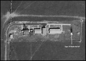
Following work by researcher
Chris Corkish, he has suggested that an RAF radar may well have been used
at the site, possibly a Type 15 with the aerial at the seaward (south east)
end. The Type 15 was installed on RN Fighter Direction Tenders so
there there is a tie-up here. He also pointed out that the building
there is very similar to a standard RAF GCI one, so I've annotated a vertical
view below with his suggestions as to the uses of the various buildings.
Hopefully Chris will publish his 'Isle of Man Military Radar' work which
he has generously shared with me.
 RAF Type 15 Radar
Station
RAF Type 15 Radar
Station
|
 The RN radar site
in 2013
The RN radar site
in 2013
|
 An elevated view
of the RN radar buildings in 2013
An elevated view
of the RN radar buildings in 2013
|
Three aerial pictures
of the RN Radar site taken in 2020
Annotated views suggesting
uses of the buildings (based on the research of Chris Corkish)
 1946 Aerial Image
|
 2020 Annotated Aerial
Image
2020 Annotated Aerial
Image
|
Carrier Controlled
Approach
An idea being developed
towards the end of WW2 was to mount a Precision Approach Radar of the newly
developed type being produced in the USA onto Royal Navy aircraft carriers.
The idea was that aircraft recovering to the ship could be directed by
radar, initially using the ships surveillance radars to sequence the aircraft
which would then be handed of to the PAR Director who would provide a 'radar
talkdown' (Ground Controlled Approach - GCA) almost onto the deck of the
ship until the pilot could see the deck and continue visually under guidance
of the Deck landing Control Officer, known as 'Bats'.
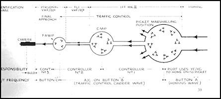 Diagram showing Carrier
Controlled Recovery Technique
Diagram showing Carrier
Controlled Recovery Technique
|
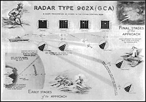 GCA recovery using
Type 962X Radar
GCA recovery using
Type 962X Radar
|
Aircraft recovering
to land would first be directed to navigate to a 'Picket Marshalling
Position', usually a radar beacon located on a destroyer or cruiser
(or for a land base the airfield located Eureka beacon could be used to
fly to a position away from the airfield awaiting radar pickup). Aircraft
would then be identified and directed using Type 293 or 277 surveillance
radar to a 'Carrier Marshalling Point' about 10 to 15 miles away
from the ship before individual flights were brought onwards to the 'Approach
Waiting Position' about 6 to 8 miles astern and held before individual
aircraft would be directed along the final approach lane using the Type
962X Ground Controlled Approach Radar until final carrier landing instructions
would be given by bat signals. At a land airfield either bat signals for
a practice carrier landing or light signals from the runway van could be
used for landing clearance. Three VHF frequencies were required:
'Button A' for homing to the Picket Marshalling Position, 'Button B' (with
two controllers using this frequency) using surveillance radar to the CMP
and then the AWP and 'Button C' for the Ground Controlled Approach 'talkdown'.
Pilots (and controllers)
would obviously require training in the new techniques and it would be
safer and cheaper to use a land base rather than an aircraft carrier for
initial training. The controllers were all former pilots who were
'grounded' for one reason or another.
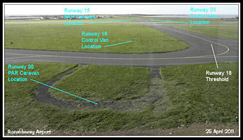
The PAR radar equipment
was installed into two vehicles that had to be positioned close to the
downwind end of the runway in use, effectively looking along the approach
course the aircraft would take. For safety reasons they weren't actually
at the end of the runway, but positioned slightly off the centreline, so
the final approach course would be on an offset to the actual runway direction.
Tarmac loops were installed at Ronaldsway for the vehicles to park on,
they are visible in the aerial photographs of the time and several are
still in existence today. Whether the PAR radar actually became operational
at Ronaldsway is not known, possibly with the end of WW2 and closure of
HMS Urley shortly after it never did.
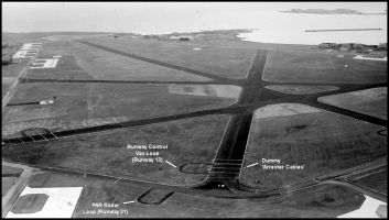 Radar and Runway
Control Van Loops c1945
Radar and Runway
Control Van Loops c1945
|
 Remains of Radar
and Control Van Loops 2011
Remains of Radar
and Control Van Loops 2011
|
AN/MPN1 Precision
Approach Radar (PAR/GCA)
The initial prototype
Precision Approach Radar equipment was designed and built by the Massachusetts
Institute of Technology (MIT) at Cambridge, Mass. and was tested in the
UK in 1942/43 at locations in Cornwall. The (later) famous author
Arthur C. Clarke was involved in these trials and subsequently wrote a
fictitious novel 'Glide Path' that was closely based on his experiences.
It impressed RAF observers and was subsequently ordered into production,
constructed by Gilfillan Bros. of Los Angeles. Nine of the Mk1 sets
were produced and three went to the RAF for trials in 1944 at RAF Hinton
on the Hedges, before soon moving to RAF Honily. The main production
design was to be the Mk2 and designated AN/MPN1.
The whole set-up was
mobile, consisting of a large truck carrying generators and air conditioning
units, together with a trailer that housed not only the two radar systems
(Search and Talkdown) but also the operators and radar displays. Three
radar aerials were mounted on it, the search radar which rotated through
360 degrees with a 6 degree beamwidth and had a range of 30nm and the two
parts of the PAR, the Azimuth aerial which tracked horizontally 20 degrees
each side of the final approach path out to 10nm and the elevation aerial
which tracked vertically by 7 degrees with a narrow horizontal beamwidth.
HF and VHF radios were fitted for communications with aircraft and the
unit would be 'plugged in' to ground telephone links to the control tower
at the operating site. It would be towed to the appropriate hard standing
for the runway in use, powered up and then aligned using radar reflectors.
The caravan also had to be tilted at the correct angle for the elevation
beam to produce the right glide path for approaching aircraft. Changing
runways would obviously take a little time.
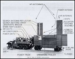 AN/MPN1 Radar Truck
& Control Caravan
AN/MPN1 Radar Truck
& Control Caravan
|
Precision Approach radar
allowed a ground controller to offer a 'talkdown' service using the radar
to guide aircraft to the runway in poor weather conditions. No specialist
equipment was required on the aircraft, just a two way radio for communications.
The radar consisted of two elements, a 'search' or surveillance radar that
scanned through 360 degrees (similar to the current radar at Ronaldsway)
and the talkdown element which scanned the final approach track with separate
horizontal and vertical radar beams. The 'search' controller would radar
identify inbound aircraft when they were within 30nm of the airfield and
marshall them onto a closing heading for the final approach track until
they came within the beam of the 'Precision Approach Radar' (PAR) at around
10nm out and the aircraft would be transferred to a separate frequency
for the talkdown. The controller would give the pilot heading corrections
to remain on the final approach track and at a predetermined point instruct
the pilot to commence descent. The controller would monitor the descent
profile and instruct the pilot to alter descent rate if the aircraft started
to drift either high or low and continue giving heading corrections to
keep the aircraft on the centreline. The talkdown would commence at about
5 miles from touchdown and be continued to 1/2 a mile from the touchdown
point although the equipment was capable of displaying the aircraft right
down to the touchdown point.
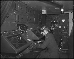 Interior of the MPN1
Control Caravan
Interior of the MPN1
Control Caravan
|
With the AN/MPN1 radar
system, the talkdown controller sat in front of the azimuth radar display
and a separate 'tracker' watched the elevation display and tracked the
aircraft blip on it with an electronic cursor, the results of which were
displayed to the controller on a meter showing any divergence from the
nominal glideslope in feet. The display CRT tubes were small and
mounted vertically showing the picture backwards, and then reflected in
a mirrors to the controllers and trackers. Presumably there was insufficient
depth within the caravan to accommodate the CRTs and associated electronics
in a more conventional format. Later developments of PAR displayed
both the azimuth and elevation elements to the controller on one CRT.
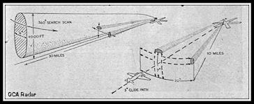 'Flight' diagram
showing the search and talkdown radar beams
'Flight' diagram
showing the search and talkdown radar beams
|
Early PAR systems used
'trackers' manning the radar tubes who keep electronic markers centred
on the aircraft return which would drive two meters in front of the controller
showing lateral and vertical displacement. In later systems the trackers
were dispensed with and the controller sat in front of a cathode ray tube
displaying both the lateral and vertical radar traces.
Other Aids to
Navigation at HMS Urley
Pundit Beacon
A red visual light beacon
that flashed an identifying code for the airfield in morse code.
Originally and subsequently located on the airfield, during wartime they
were sometimes moved away to one of three known locations at some distance
from the actual airfield to confuse the enemy. HMS Urley's beacon flashed
the letters 'RX'. Post WW2 most airfields had them, with red lights
for military airfields and green for civil.
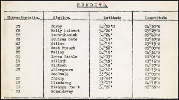 Table of Pundit Beacons
around the Irish Sea
Table of Pundit Beacons
around the Irish Sea
|
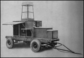 A mobile Pundit Light
Beacon
A mobile Pundit Light
Beacon
|
VHF D/F
Radio direction finding
had been in use since the early days of radios in aircraft, with specialist
D/F operators taking manual bearings on aircraft transmissions and then
passing then to either the pilots or controllers, but with the advent of
VHF radios Cathode Ray Direction Finding (CRDF) came into use giving the
controller an instant display of an aircraft's transmission on a Cathode
Ray Tube. As the aircraft transmitted, a trace would appear on the
display and the bearing read off against a compass rose. The most
likely unit to be installed was an FV5 which covered frequencies from 100
to 150MHz. Bearings from the airfield could be passed to aircraft
to assist with navigation or alternatively, bearings to the airfield to
allow inbound aircraft to 'home' and let down to known safe sector altitudes
until they had the airfield in sight and could continue visually.
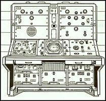 FV5 control and indicator
desk
FV5 control and indicator
desk
|
 VHF D/F aerial on
Ronaldsway Control Tower
VHF D/F aerial on
Ronaldsway Control Tower
|
YG Radio Beacon
A radio beacon widely
used by the Fleet Air Arm both on ships and land bases was 'YE and YG'.
This was a system developed for the United States Navy and replaced a similar
earlier UK developed one, the advantage being that USN and RN aircraft
could use each other's beacons. The YE beacon was mainly deployed
on ships as it was linked into the ships gyro compass to keep the beacon
correctly aligned to true north as the ship turned. The YG beacon needed
manual alignment which of course wasn't a problem on a land base, it could
be in a fixed position or a mobile installation mounted on a vehicle. The
beacon worked on a fixed frequency in the 234 - 258 MHz range which could
be changed in a hostile environment but in peacetime 246 MHz was used.
All beacons worked on the same frequency which had to be manually set in
the aircraft before flight, as it couldn't be changed once in the air.
The transmission on each beacon was modulated on one of six frequencies
between 660 KHz and 810 KHz (RN use) identified by Channel numbers
and selected in the aircraft cockpit, Ronaldsway was on Channel Two.
The ground beacon had a mechanically rotated aerial at two RPM which transmitted
a single morse code letter depending on the direction that it was facing.
Every five minutes (on the tenth rotation) it would transmit a two letter
identification code. It could also transmit voice messgaes if required.
The only other station likely to be received on channel two in the IOM
area would be Ayr, so if to the north of the island at altitude correct
identification of the beacon was important, it would be embarrasing to
arrive at the wrong airfield!
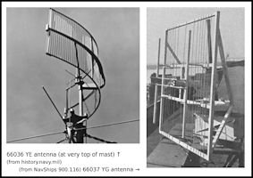 YE and YG beacon
aerials
YE and YG beacon
aerials
|
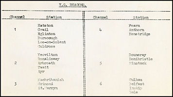 Table of YG Beacons
|
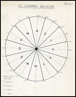 YG Sector Decode
Chart
YG Sector Decode
Chart
|
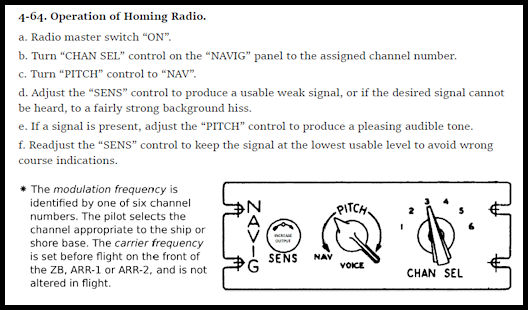 Aircraft equipment
operating instructions.
Aircraft equipment
operating instructions.
|
To use the beacon the
pilot would turn on the aircraft receiver and select the appropriate channel
for the beacon required. Initially many of the sector codes would be heard
and he would turn down the sensitivity control on the set until he could
hear just three which would place him in the centre sector of the three.
For example, homing to Ronaldsway from somewhere to the south; select Channel
Two and identify the beacon. Turn down the sensitivity until only three
sector codes can be heard, e.g. M N & R. Using the chart this places
the aircraft to the south west of Ronaldsway in the 'N' sector and the
pilot has to steer a course between 028 and 058 degrees to home to base.
As the aircraft flew closer to the beacon the sectors narrowed and course
corrections were applied to keep in the required sector, the receiver sensitivity
being progressively reduced until only one letter could be heard. The aircraft
could be descended in accordance with terrain safe levels until the airfield
was sighted or reception of all the letters with sensitivity to minimum
indicated arrival in the overhead. Presumably if homing to Ronaldsway from
the north (over the hills), once having passed though the overhead at terrain
safe level a course could be selected to let down further over the sea.
The advantage of YG
over other homing methods was that it was independent of the other aircraft
radios so could be used in a radio failure situation and compared to medium
frequency non-directional beacons gave a course indication for safe descent.
In many respects it could be considered a precursor of today's VOR beacons.
In miltary service it was replaced by TACAN beacons in the 1950s
(I am indebted to Lieut.
Richard Collins RNVR via the Airfield
Information Exchange for the operating description of YG
and to Paul Smith for
a lot more information on it and extra illustrations)
Eureka, Rebecca &
Babs
Also installed at Ronaldsway
was Eureka, a ground radar beacon that could be interrogated by airborne
radar. the aircraft navigator could provide a 'talk down' service to his
pilot by interpreting the returns on the aircraft radar set.
There were three elements
of this radar homing and approach aid operating on frequencies around 200
MHz. Eureka was the ground based radar responder beacon. Rebecca was the
aircraft fitted element of the system and would interrogate the Eureka
beacon to obtain a range and bearing from the airfield to enable the aircraft
to home in. Babs was the approach element and when interrogated by Rebecca
would provide an indication of final approach track and distance from the
airfield. This was presented to the aircraft navigator on the airborne
radar CRT screens and the navigator would talk the pilot down until he
became visual with the runway. The Ronaldsway based RN Barracuda aircraft
would most likely have been fitted with Rebecca Mk11B.
Link
to external page with details of Eureka/Rebecca/Babs
The Royal Navy Depart
Only just over a year
after HMS Urley had opened for operations at what must have been a huge
expense, WW2 ended on 15th August 1945, and the need for intensive training
of crews vanished overnight. The establishment started to be run
down with 747 NAS leaving on the 15th November although their 'B' flight
remained with Avro Ansons. All training finished on 20th December when
710 and 713 squadrons were disbanded together with 747 NAS 'B' flight.
HMS Urley was officially decommissioned on the 14th January 1946 and the
airfield was handed over to the UK Ministry of Civil Aviation. All of the
Royal Navy radar aids would also have been removed at this time.
At some point in 1946 the civil control moved from the barn site to the
former Royal Navy control tower on the north side - and could at last see
what was happening on the runways and taxiways!
Post War Civil Operations at
Ronaldsway
After initially being
operated by the UK Ministry of Civil Aviation, Ronaldsway was bought by
the Isle of Man Government who took possession on the 1st March 1948. A
new 'North West Flight Safety Region' was established to replace the old
pre war Communications Area. This was administered from Liverpool Speke
airport using M/F frequencies 339-341 KHz. Meanwhile the UK governments
of the day tried to decide on how to organize air traffic control in the
future. With a flood of cheap ex service transport aircraft such as the
Douglas Dakota, becoming available plus crews to fly them it looked like
the skies could become much busier.
At Ronaldsway In the
late 1940s Air Traffic Control was being carried out much as in the pre
war days with the Control Zone re-instated to 10 miles around the airport
but only active in low visibility or low cloud 'QBI'. Communications were
still mainly by W/T on Medium (M/F) and High (H/F) frequencies, but with
more aircraft being equipped with VHF Speech telephony which enabled the
controllers to talk to pilots directly, the days of the specialized radio
operators were numbered. Ronaldsway is shown equipped with one VHF
radio frequency (118.1 MHz) on the 1948 charts shown below. A Plessey
122R Radio Direction Finder was installed in the control tower. To
contradict the chart information an article entitled ' Telecommunications
at Ronaldsway' published in the 1980s states that the former RN sites at
Orrisdale and Phildraw had been brought back into service to 'provide the
airport with four VHF Radio Telephony frequencies'. It seems extreemly
unlikely that Ronaldsway would in fact requir four separate frequencies
so most likely there were in fact two frequencies, one for Tower and one
for Approach, but with duplicated equipment on each frequency. The
article also states that a VHF Direction Finder was in use at Orrisdale.
M/F Direction
Finding stations at Speke, Ronaldsway, Carlisle and Manchester Ringway
could provide bearings to plot aircraft positions. Presumably 'traffic
information' would be provided on other aircraft, but it was up to pilots
to arrange their own separation, either visually or by flying at different
heights. Ronaldsway ATC would provide control services within its 10nm
Controlled Zone in 'QBI'.
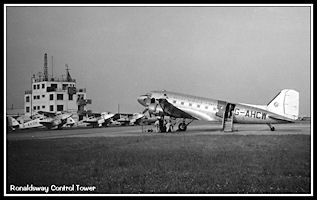 BEA Dakota G-AHCW
with Dragon Rapides behind.
Picture taken between
1946 and 1949
BEA Dakota G-AHCW
with Dragon Rapides behind.
Picture taken between
1946 and 1949
|
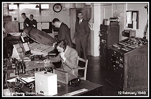 Ronaldsway Control
Room 1948
Ronaldsway Control
Room 1948
|
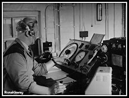 Ronaldsway M/F Radio
Direction Finder
Ronaldsway M/F Radio
Direction Finder
|
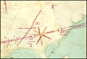 Ronaldsway Airfield
Diagram - August 1948
Ronaldsway Airfield
Diagram - August 1948
|
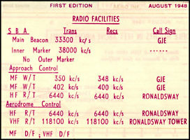 Ronaldsway Radio
Facilities - August 1948
Ronaldsway Radio
Facilities - August 1948
|
Phonetic Alphabets
With the use of telephony
instead of telegraphy there is a need to be able to clearly spell out the
letters of the alphabet. A system of using a full word to indicate
a letter had been originated for use by the Royal Navy before World War
1 and the RAF produced their own by 1924. The original RAF phonetic
alphabet was used until changed 1943 and then continued in use post war.
The USA used a very similar one but during the early 1950s several different
ones were tested with varying success until the current one was adopted
in the mid 1950s. Four versions are shown below.
|
1914 -18 Royal Navy
|
1924 - 1942 RAF
|
1943 - 1956 RAF
|
ICAO/NATO Present
Day
|
|
Apples
|
Ace
|
Able
|
Alpha
|
|
Butter
|
Beer
|
Baker
|
Bravo
|
|
Charlie
|
Charlie
|
Charlie
|
Charlie
|
|
Duff
|
Don
|
Dog
|
Delta
|
|
Edward
|
Edward
|
Easy
|
Echo
|
|
Freddy
|
Freddie
|
Fox
|
Foxtrot
|
|
George
|
George
|
George
|
Golf
|
|
Harry
|
Harry
|
How
|
Hotel
|
|
Ink
|
Ink
|
Item
|
India
|
|
Johnnie
|
Johnnie
|
Jig
|
Juliet
|
|
King
|
King
|
King
|
Kilo
|
|
London
|
London
|
Love
|
Lima
|
|
Monkey
|
Monkey
|
Mike
|
Mike
|
|
Nuts
|
Nuts
|
Nab
|
November
|
|
Orange
|
Orange
|
Oboe
|
Oscar
|
|
Pudding
|
Pip
|
Peter
|
Papa
|
|
Queenie
|
Queen
|
Queen
|
Quebec
|
|
Robert
|
Robert
|
Roger
|
Romeo
|
|
Sugar
|
Sugar
|
Sugar
|
Sierra
|
|
Tommy
|
Toc
|
Tare
|
Tango
|
|
Uncle
|
Uncle
|
Uncle
|
Uniform
|
|
Vinegar
|
Vic
|
Victor
|
Victor
|
|
Willie
|
William
|
William
|
Whiskey
|
|
Xerxes
|
X-Ray
|
X-Ray
|
X-Ray
|
|
Yellow
|
Yorker
|
Yoke
|
Yankee
|
|
Zebra
|
Zebra
|
Zebra
|
Zulu
|
Standard Approaches Mandated
Towards the end of the
1940s a major change was introduced in the UK regarding how pilots were
to fly instrument approaches. Before, it had been entirely up to the pilot
as to where he let down through cloud and to what altitude. During WW2
the RAF had instigated a rudimentary system of instrument letdowns know
as QGH approaches, based on the controller interpreting Direction Finder
bearings and instructing pilots to fly certain headings and levels. This
was mainly to de-conflict military aircraft returning to bases often only
a few miles apart and prevent aerial collisions. This principle was extended
to civil aviation and defined instrument approaches published to airfields
showing courses to be flown, together with set altitudes for each 'leg'
of the procedure. This also enabled traffic levels to be increased, as
controllers could now hold aircraft inside the Controlled Zone, spaced
at 500 ft vertical intervals, each aircraft taking its turn to fly the
instrument approach. As a level was reported vacated, each aircraft above
could be stepped down awaiting its turn for the approach. Minimum safe
levels for descent were published for each approach taking into account
the accuracy of the approach facility and terrain surrounding the airport.
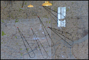
|
RAF 'Safety Let Down
Lanes'
Map at the Yorkshire
Air Museum
showing the 'Safety
Let Down Lanes' to
QGH or SBA approaches
at WW2 military airfields in South Yorkshire
|
Ronaldsway Standard Beam Approach
By August 1948 a Standard
Beam Approach (SBA) system had been installed at Ronaldsway. This
was based on the pre war 'Lorenz' system that had been used at Croydon
Airport, London, in the 1930s. It operated on the low VHF frequency
of 33.3 MHz for the Main Beacon and 38.0 MHz for the Inner Marker Beacon
which was located just short of the runway 27 threshold. In many
ways the forerunner of current Instrument Landing Systems (ILS), but using
audio tones rather than a visual instrument in the cockpit, although they
were also available. (See ATC
1930s pages for illustrations). The pilot would fly on predetermined
tracks, timed on a stopwatch, to align with the final approach course.
If he was to the right of track he would hear a Morse letter 'N' (- .)
in his headphones. If to the left he would hear letter 'A' (. -) and when
on the final track the two letters would combine to produce a continuous
tone. The system was aligned with Runway 27 at Ronaldsway, but a
'Back Beam' approach could also be flown to position for Runway 09.
On the Back Beam approach the audio Morse letters would be reversed.
On approach for Runway 27 pilots were allowed to let down to 200 ft on
instruments before breaking off the approach if the runway wasn't sighted,
but on Runway 09 the break off height was 700 ft.
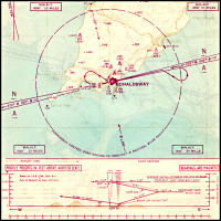 Ronaldsway SBA Front
Beam (plan & vertical profile)
Ronaldsway SBA Front
Beam (plan & vertical profile)
|
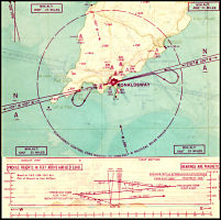 Ronaldsway SBA Back
Beam (plan & vertical profile)
Ronaldsway SBA Back
Beam (plan & vertical profile)
|
ATC
in the 1950s
|
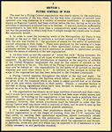
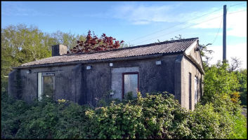
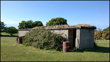
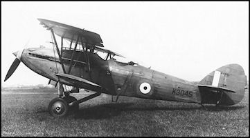
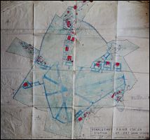
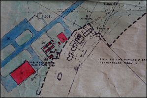
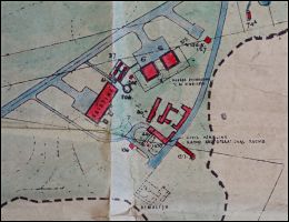
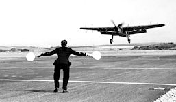
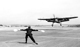
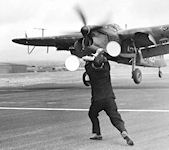
m.jpg)
m.jpg)
m.jpg)